Land Rover Discovery: Oil Pan
.jpg)
- Flange bolt
- Sprocket
- Variable flow oil pump with integral vacuum pump
- Oil level gauge
- Oil level gauge tube
- Bolt (4 off)
- Oil pan
- Bolt (16 off)
- Sealing washer
- Drain plug
The oil pan is cast from aluminum alloy using a high pressure die cast process and is located on the underside of the cylinder block. It is sealed to the cylinder block with a 3 mm bead of RTV sealant and secured with fourteen bolts and two shoulder bolts that help locate the oil pan to the block. The oil pan contains the variable flow oil pump with integral vacuum pump, pick up pipe, windage tray and dipstick. The oil is drained via removal of a drain plug and washer located on the side of the oil pan.
CYLINDER HEAD
.jpg)
- Screw (10 off)
- Chain cover and gasket
- Camshaft carrier
- Engine vent module
- Screw (8 off)
- Exhaust camshaft
- Camshaft caps (8 off0)
- Screw (20 off)
- Roller finger cam follower (16 off)
- Inlet and exhaust valve assemblies (16 off)
- Cylinder head gasket
- Cylinder head
- Screw (4 off)
- Cylinder head bolt (10 off)
- Camshaft cap
- Variable Camshaft Timing (VCT) actuator
- Inlet camshaft
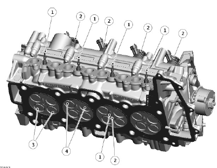
The cylinder head is cast from aluminum alloy and heat treated. The cylinder head provides location for sixteen valves, four injectors, four glow plugs and one cylinder head temperature sensor. The cylinder head is cooled by a double layer water jacket. Each cylinder has four valves.
Each cylinder is served by four valves. To help achieve the required gas-flow characteristics, the cylinder head has two inlet ports and two exhaust ports arranged asymmetrically around each cylinder bore. The four centrally mounted injectors are located on the upper side of the cylinder head and direct fuel into the combustion chamber. The injectors are retained in the cylinder head by injector clamps and screws located on the camshaft carrier.
To help achieve the required gas-flow characteristics, the fuel injectors are mounted centrally in the combustion chamber.
Four glow plugs are located in the cylinder head. The glow plugs fit into threaded ports between the inlet port for each cylinder, allowing the tip of each glow plug to protrude into the combustion chamber.
- Glow plug (4 off)
- Fuel injector (4 off)
- Inlet valves (8 off)
- Exhaust valves (8 off)
The aluminum cylinder head is designed to react to the high diesel combustion cylinder pressures, while also providing a platform onto which the structural camshaft carrier can be mounted.
The cylinder head gasket is of a multi-layer steel construction.
READ NEXT:
 Camshaft Carrier
Fuel rail
Fuel injector (4 off)
Oil filler and cap assembly
Engine vent module
Engine breather pipe
Camshaft carrier
Exhaust camshaft and Variable Camshaft Timing (VCT) actuator
Inlet camsh
Variable Сamshaft Еiming (VCT) - Exhaust Camshaft Only
Exhaust VCT solenoid
Exhaust VCT actuator
The timing of the exhaust camshaft can be adjusted independently by an oil
pressure controlled torsional assist VCT system. The VCT solenoid which is
co
Variable Flow Oil Pump With Integral Vacuum Pump
Vacuum exhaust valve
Pressurized oil outlet to cylinder block
Center plate
Oil pressure control solenoid
Control ring
Vanes and rotor assembly
Oil pump cover
Control spring
Oil pump housin
SEE MORE:
Front end Sheet Metal
Repairs Front
Fender Mounting
Panel (G1770874) / Removal
and Installation
REMOVAL
NOTE:
The front fender mounting panel is installed in conjunction with:
Front fender
Front door
The front fender mounting panel is serviced as indicated.
Before commencing this procedure make sure that you are aware of
all Health and Safety requirements.
For additional information
Park Lock
Park lock lever - Connection with park lock actuator spool valve
Selector shaft Service Park Release (SPR) lever
Park rod
Spring
Park lock pawl
Spring
Differential spur gear
Park lock gear
Park lock lever - Connection with PARK (P) sensor
The park lock comprises a selector shaft, a park
