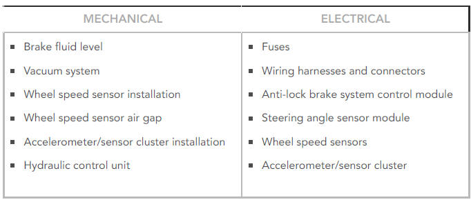
Land Rover Discovery: Anti-lock Control - Traction Control / Diagnosis and Testing
PRINCIPLES OF OPERATION
For a detailed description of the Anti-lock Brake System, refer to the relevant Description and Operation section in the workshop manual. REFER to: Anti-Lock Control - Traction Control (206-09B Anti-Lock Control - Traction Control, Description and Operation).
INSPECTION AND VERIFICATION
CAUTION:
Diagnosis by substitution from a donor vehicle is NOT acceptable.
Substitution of control modules does not guarantee confirmation of a fault, and may also cause additional faults in the vehicle being tested and/or the donor vehicle.
NOTES:
- If a control module or a component is suspect and the vehicle remains under manufacturer warranty, refer to the Warranty Policy and Procedures manual, or determine if any prior approval programme is in operation, prior to the installation of a new module/component.
- When performing voltage or resistance tests, always use a digital
multimeter that has the resolution ability to view 3 decimal places.
For example, on the 2 volts range can measure 1mV or 2 K Ohm range can measure 1 Ohm. When testing resistance always take the resistance of the digital multimeter leads into account.
- Check and rectify basic faults before beginning diagnostic routines involving pinpoint tests.
- Verify the customer concern
- Visually inspect for obvious signs of damage and system integrity
Visual Inspection
- If an obvious cause for an observed or reported concern is found, correct the cause (if possible) before proceeding to the next step
- If the cause is not visually evident, verify the symptom and refer to the Symptom Chart, alternatively check for Diagnostic Trouble Codes (DTCs) and refer to the DTC Index
- Check DDW for open campaigns. Refer to the corresponding bulletins and SSMs which may be valid for the specific customer complaint and carry out the recommendations as required
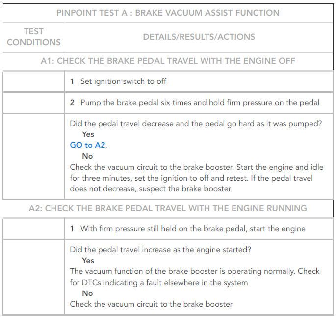
PINPOINT TESTS
DTC INDEX
For a list of Diagnostic Trouble Codes (DTCs) that could be logged on this vehicle, please refer to Section 100-00. REFER to: Diagnostic Trouble Code Index - DTC: Anti-lock Braking System Control Module (ABS) (100-00 General Information, Description and Operation).
Anti-lock control specifications
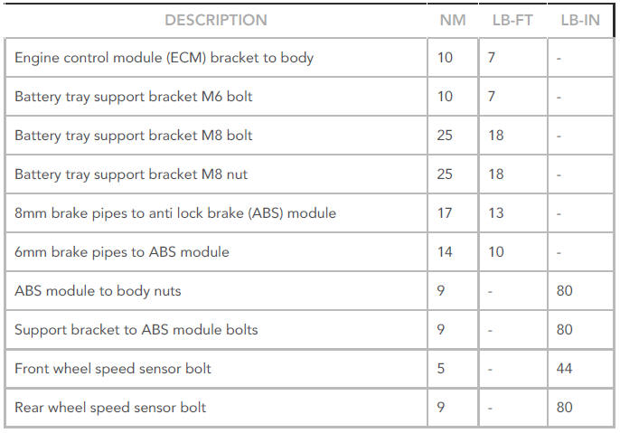
Torque Specifications
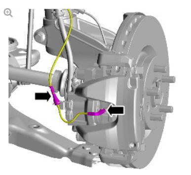
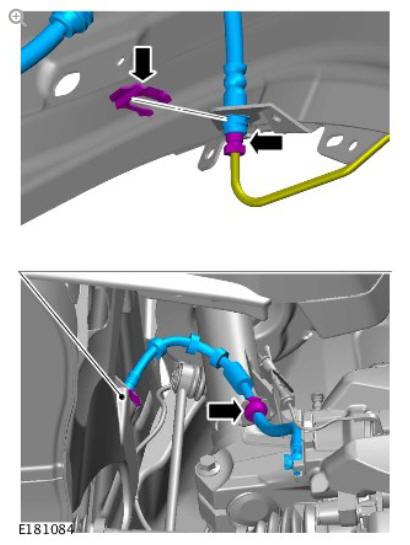
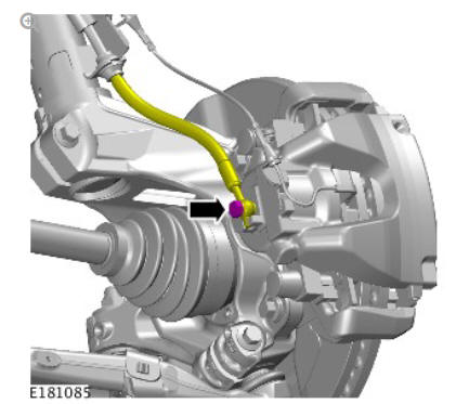
Front disc brake brake caliper (G1785105) removal and installation
REMOVAL
CAUTION:
If brake fluid is spilt on the paintwork, the affected area must be immediately washed down with cold water.
WARNING:
Make sure to support the vehicle with axle stands.
Raise and support the vehicle.
Refer to: Wheel and Tire (204-04 Wheels and Tires, Removal and Installation).
CAUTION:
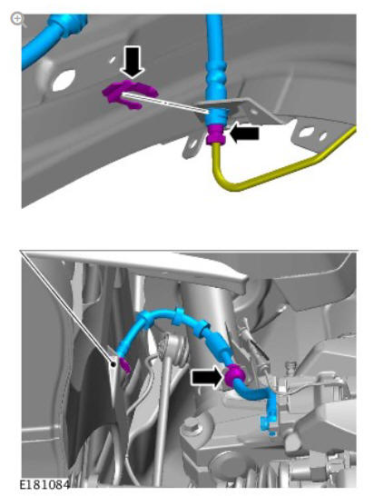
If the brake hose banjo bolt has been loosened or removed, a new brake hose assembly must be installed

CAUTIONS:
- Be prepared to collect escaping fluids.
- Make sure that all openings are sealed. Use new blanking caps.
NOTE:
The flexible brake hose with washers and the banjo bolt is only available as an assembly.
INSTALLATION
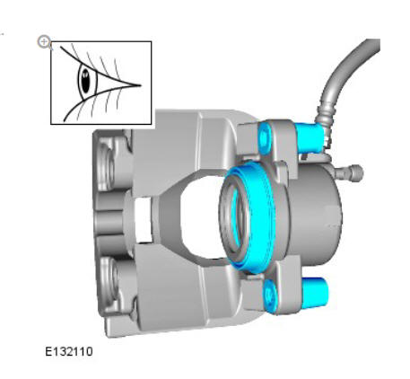
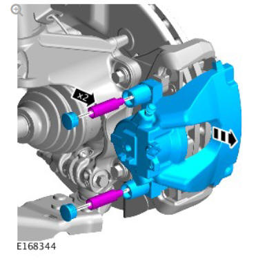
Inspect the caliper piston and slide pin seals for damage.
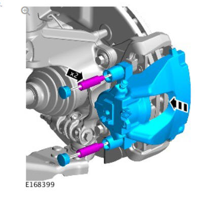
Torque: 58 Nm
NOTE:
Remove and discard all blanking caps.
Torque: 15 Nm
CAUTION:
Make sure that the brake hose is not twisted and is correctly located.
Torque: 32 Nm
Refer to: Brake System Bleeding (206-00 Brake System - General Information, General Procedures).
Refer to: Wheel and Tire (204-04 Wheels and Tires, Removal and Installation).
READ NEXT:
 Front Disc Brake Brake Caliper Anchor Plate (G1785106) / Removal and
Installation
Front Disc Brake Brake Caliper Anchor Plate (G1785106) / Removal and
Installation
PART(S)
REMOVAL
NOTE:
Removal steps in this procedure may contain installation details.
WARNING:
Make sure to support the vehicle with axle stands.
Raise and support the vehicle
Refer to: Wheel and T
Front Disc Brake Brake Disc (G1785104) / Removal and Installation
PART(S)
REMOVAL
WARNING:
If installing a new brake disc, install new brake pads.
CAUTION:
Brake discs must be renewed in pairs.
NOTE:
Left hand illustration shown, Right hand is similar.
WARNING:
Ma
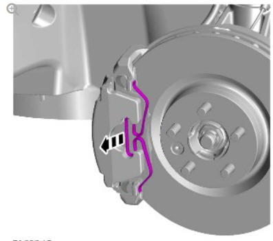
Front Disc Brake Brake Pads (G1785103) / Removal and Installation
REMOVAL
WARNING:
Brake pads must be renewed in axle sets only. Failure to follow this
instruction may result in braking efficiency being impaired.
NOTES:
Left illustration shown, right is similar.
SEE MORE:
Auxiliary Battery (G1913471) /
Removal and
Installation
REMOVAL
NOTE:
Removal steps in this procedure may contain installation details.
Disconnect the battery earth lead.
Refer to: Specifications (414-01 Battery, Mounting and Cables,
Specifications).
Refer to: Plenum Chamber (412-01 Climate Control, Removal and
Installation).
Torque: 10 Nm
Torque: 1
Manual Transmission - Transaxle
External Controls
Gearshift Linkage (G1781377)
/ Removal and Installation
REMOVAL
NOTES:
Removal steps in this procedure may contain installation details.
Some variation in the illustrations may occur, but the essential
information is always correct.
CAUTION:
Make sure that Neutral is selected before starting the
procedure.
Refer to: Air Cleaner (303-12, Removal an
