Land Rover Discovery: Front Disc Brake Brake Pads (G1785103) / Removal and Installation
REMOVAL
WARNING:
Brake pads must be renewed in axle sets only. Failure to follow this instruction may result in braking efficiency being impaired.
NOTES:
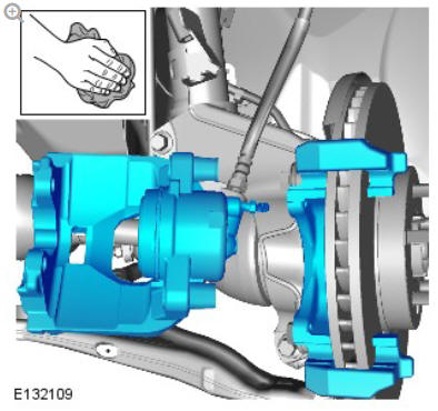
- Left illustration shown, right is similar.
- Some variation in the illustrations may occur but the essential information is always correct.
WARNING:
Make sure to support the vehicle with axle stands.
Raise and support the vehicle.
Refer to: Wheel and Tire (204-04 Wheels and Tires, Removal and Installation).
CAUTION:
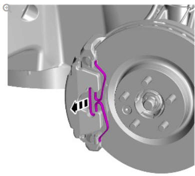
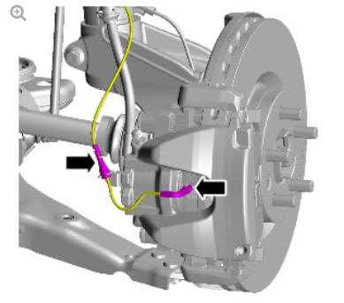
Do not allow the brake caliper to hang on the brake hose.
Tie aside.
INSTALLATION
WARNING:
Do not use compressed air to clean brake components. Dust from friction materials can be harmful if inhaled.
CAUTION:
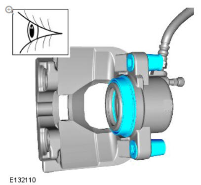
Make sure that the mating faces are clean and free of foreign material and that no grease is applied to the brake pad guides.
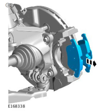
Clean the brake caliper housing and anchor plate using brake cleaning fluid.
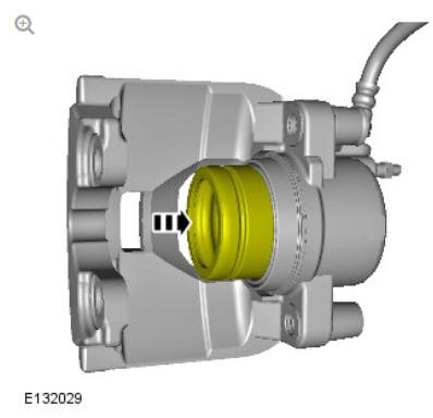
- Inspect the caliper piston and slide pin seals for damage.
.jpg)
CAUTION:
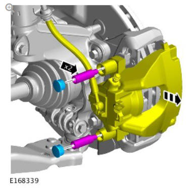
Make sure that the brake hose is not twisted and is correctly located.
.jpg)
Torque: 58 Nm
.jpg)
.jpg)
Refer to: Wheel and Tire (204-04 Wheels and Tires, Removal and Installation).
Repeat the above procedure for the other side.
Depress the brake pedal several times, check the fluid level in the brake fluid reservoir and top-up with brake fluid if necessary.
Front disc brake specifications
General specifications
.jpg)
Torque Specifications
.jpg)
.jpg)
READ NEXT:
 General Information Brake System Bleeding (G1785100) / General Procedures
NOTES:
Bleeding of the complete brake system must be carried out using
Land Rover approved diagnostic equipment. Where only the
primary or secondary brake circuits have been disturbed in
isolatio
General Information Brake System Pressure Bleeding (G1785101) / General
Procedures
BLEEDING
NOTE:
Some variation in the illustrations may occur, but the essential
information is always correct.
All vehicles
WARNING:
Make sure to support the vehicle with axle stands.
Raise and suppor
General Information Front Brake Disc Runout Check (G2010035) / General
Procedures
SPECIAL TOOL(S)
CHECK
NOTES:
Some variation in the illustrations may occur, but the essential
information is always correct.
Left shown, Right is similar.
WARNING:
Make sure to support the vehi
SEE MORE:
Front Row Seat
Head Restraint (G1780398)
/ Removal and Installation
REMOVAL
NOTES:
Some variation in the illustrations may occur, but the essential
information is always correct.
Removal steps in this procedure may contain installation details.
Refer to: Front Row Seat - Vehicles With: Power Seats (501-10
Seating, Removal and Installation).
INST
Steering Linkage Tie
Rod (G1788230) / Removal and
Installation
SPECIAL TOOL(S)
REMOVAL
NOTES:
Some components shown removed for clarity.
Removal steps in this procedure may contain installation details.
Refer to: Steering Gear Boot (211-03 Steering Linkage, Removal
and Installation).
Special Tool(s): JLR-211-342
CAUTION:
Make sure the steering gear ba
