Land Rover Discovery: Fuel Tank and Lines - Ingenium i4 2.0l Diesel Diagnosis and Testing
PRINCIPLE OF OPERATION
For a detailed description of the fuel tank and lines system and operation, refer to the relevant Description and Operation section of the workshop manual. REFER to: (310-01B Fuel Tank and Lines - INGENIUM I4 2.0L Diesel)
Fuel Tank and Lines (Description and Operation), Specifications (Specifications), Fuel Pump and Sensor Unit (Removal and Installation).
INSPECTION AND VERIFICATION
WARNINGS:
- Do NOT carry out any work on the fuel system with the engine running. The fuel pressure within the system can be as high as 2200 bar (31,908 lb/in²). Failure to follow this instruction may result in personal injury.
- Eye protection must be worn at all times when working on or near any fuel related components. Failure to follow this instruction may result in personal injury.
- This procedure involves fuel handling. Be prepared for fuel spillage at all times and always observe fuel handling precautions. Failure to follow this instruction may result in personal injury.
- After carrying out repairs, the fuel system must be checked visually for leaks. This should be done after the engine has been run, but with the engine switched OFF. Failure to follow this instruction may result in personal injury.
- If taken internally, DO NOT induce vomiting. Seek immediate medical attention. Failure to follow this instruction may result in personal injury.
- If fuel contacts the eyes, flush the eyes with cold water or eyewash solution and seek medical attention. Failure to follow this instruction may result in personal injury.
- Wash hands thoroughly after handling, as prolonged contact may
cause irritation. Should irritation develop, seek medical attention.
Failure to follow this instruction may result in personal injury.
CAUTIONS:
- Before disconnecting any part of the system, it is imperative that all dust, dirt and debris is removed from around components to prevent ingress of foreign matter into the fuel system. Failure to follow this instruction may result in damage to the vehicle.
- It is essential that absolute cleanliness is observed when working with these components. Always install blanking plugs to any open orifices or lines. Failure to follow this instruction may result in damage to the vehicle.
- Diagnosis by substitution from a donor vehicle is NOT acceptable.
Substitution of control modules does not guarantee confirmation of a fault, and may also cause additional faults in the vehicle being tested and/or the donor vehicle.
NOTES:
- Check and rectify basic faults before beginning diagnostic routines involving pinpoint tests.
- When measuring fuel sender resistance values with a multimeter, it
is critical to use the correct multimeter setting. The multimeter
should not be on the 'Auto' setting and must be set to 'Manual'.
This will help prevent incorrect diagnosis and unnecessary replacement of fuel senders. If the multimeter range is set at 'Auto' then, during a sweep of the sender from 50 Ohms to 998 Ohms, the multimeter has to change its measurement range. For approximately 1 second, during the range switch over point, the multimeter display indicates an open circuit. This can lead to a misdiagnosis of a fuel sender fault.
- Verify the customer concern
- Visually inspect for obvious signs of damage and system integrity
Visual Inspection
.jpg)
- If an obvious cause for an observed or reported concern is found, correct the cause (if possible) before proceeding to the next step
- If the cause is not visually evident, verify the symptom and refer to the Symptom Chart, alternatively check for Diagnostic Trouble Codes (DTCs) and proceed to the DTC Index
SYMPTOM CHART
.jpg)
.jpg)
SYMPTOM:
Fuel gauge reading too low
POSSIBLE CAUSES:
- Instrument Cluster (IC) is not configured correctly
- Fuel pump module flange electrical connector short circuit to ground due to frayed, melted wires/connectors or corroded connector pins
- Fuel level sensor short circuit to ground, low resistance
- Fuel level sensor float arm broken or bent Fuel level sensor failure
ACTION:
- GO to Pinpoint Test A.
SYMPTOM:
Fuel gauge reading too high
POSSIBLE CAUSES:
- Instrument Cluster (IC) is not configured correctly
- Fuel pump module flange electrical connectors short circuit to power due to melted wires/connectors or corroded connector pins
- Corroded electrical harness connections between low pressure fuel pump and Central Junction Box (CJB)
- Corroded electrical harness connections between Body Control Module (BCM) and Engine Control Module (ECM) or Instrument Cluster (IC)
- Fuel level sensor circuit short to ground
- Fuel level sensor failure
- Fuel level sensor float arm jammed in the up position
ACTION:
- GO to Pinpoint Test A.
SYMPTOM:
Fuel gauge intermittent or inconsistent
POSSIBLE CAUSES:
- Fuel level sensor poor ground connection, open circuit to power, high resistance
- Fuel pump module electrical connector open circuit to power due to frayed, melted wires/connectors or corroded connector pins
- Fuel pump module flange pins not projecting sufficiently to ensure electrical contact
- Harness electrical connectors not correctly located, disconnected, damaged or pins backed out
ACTION:
- GO to Pinpoint Test B.
SYMPTOM:
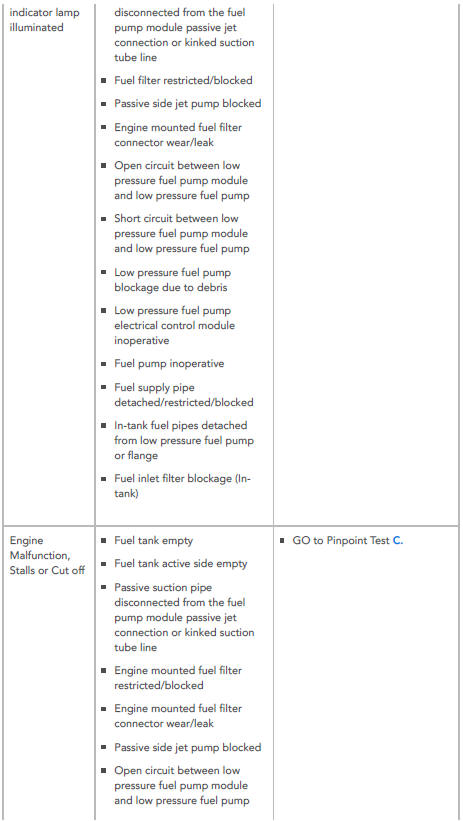
Engine cranks but will not start or malfunction indicator lamp illuminated
POSSIBLE CAUSES:
- Fuel tank empty
- Fuel tank active side empty
- Passive suction pipe disconnected from the fuel pump module passive jet connection or kinked suction tube line
- Fuel filter restricted/blocked
- Passive side jet pump blocked
- Engine mounted fuel filter connector wear/leak
- Open circuit between low pressure fuel pump module and low pressure fuel pump
- Short circuit between low pressure fuel pump module and low pressure fuel pump
- Low pressure fuel pump blockage due to debris
- Low pressure fuel pump electrical control module inoperative
- Fuel pump inoperative
- Fuel supply pipe detached/restricted/blocked
- In-tank fuel pipes detached from low pressure fuel pump or flange
- Fuel inlet filter blockage (Intank)
ACTION:
- GO to Pinpoint Test C.
SYMPTOM:
Engine Malfunction, Stalls or Cut off
POSSIBLE CAUSES:
- Fuel tank empty
- Fuel tank active side empty
- Passive suction pipe disconnected from the fuel pump module passive jet connection or kinked suction tube line
- Engine mounted fuel filter restricted/blocked
- Engine mounted fuel filter connector wear/leak
- Passive side jet pump blocked Open circuit between low pressure fuel pump module and low pressure fuel pump
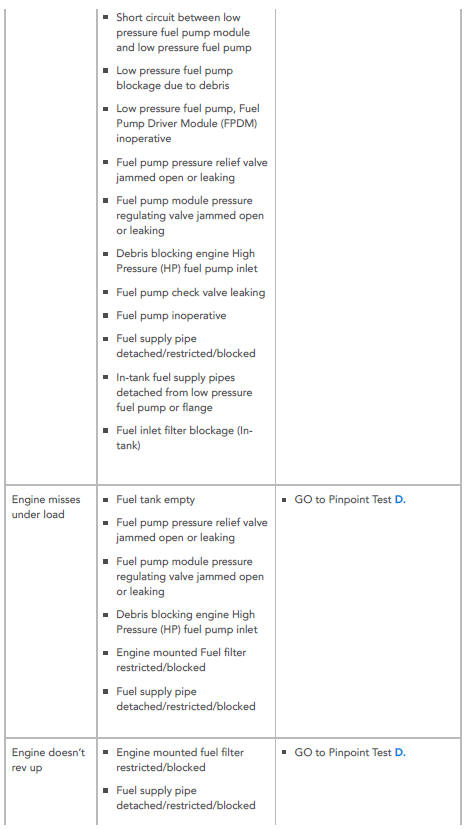
- Short circuit between low pressure fuel pump module and low pressure fuel pump
- Low pressure fuel pump blockage due to debris
- Low pressure fuel pump, Fuel Pump Driver Module (FPDM) inoperative
- Fuel pump pressure relief valve jammed open or leaking
- Fuel pump module pressure regulating valve jammed open or leaking
- Debris blocking engine High Pressure (HP) fuel pump inlet
- Fuel pump check valve leaking
- Fuel pump inoperative
- Fuel supply pipe detached/restricted/blocked
- In-tank fuel supply pipes detached from low pressure fuel pump or flange
- Fuel inlet filter blockage (Intank)
ACTION:
- GO to Pinpoint Test C.
SYMPTOM:
Engine misses under load
POSSIBLE CAUSES:
- Fuel tank empty
- Fuel pump pressure relief valve jammed open or leaking
- Fuel pump module pressure regulating valve jammed open or leaking
- Debris blocking engine High Pressure (HP) fuel pump inlet
- Engine mounted Fuel filter restricted/blocked
- Fuel supply pipe detached/restricted/blocked
ACTION:
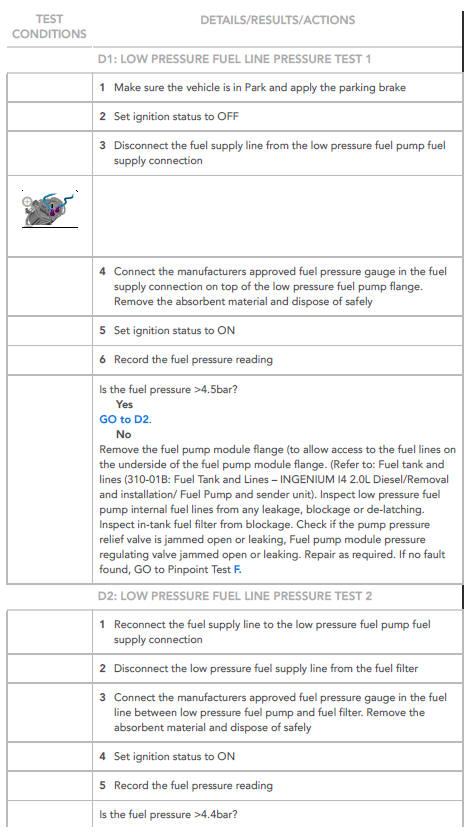
GO to Pinpoint Test D.
SYMPTOM:
Engine doesn't rev up
POSSIBLE CAUSES:
- Engine mounted fuel filter restricted/blocked
- Fuel supply pipe detached/restricted/blocked
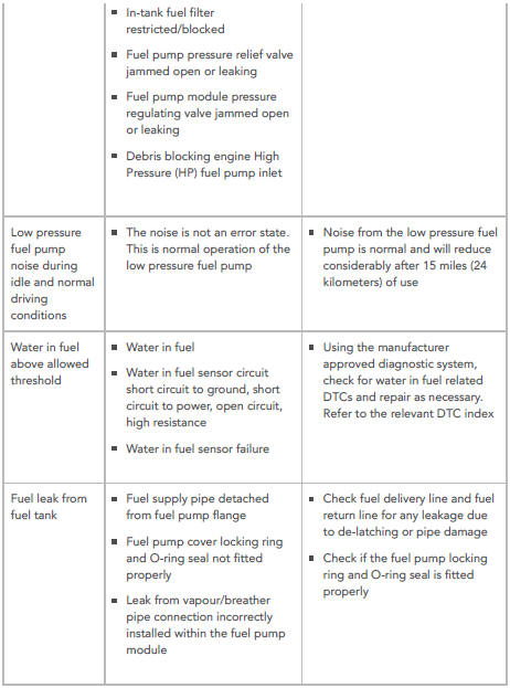
- In-tank fuel filter restricted/blocked
- Fuel pump pressure relief valve jammed open or leaking
- Fuel pump module pressure regulating valve jammed open or leaking
- Debris blocking engine High Pressure (HP) fuel pump inlet
ACTION:
- GO to Pinpoint Test D.
SYMPTOM:
Low pressure fuel pump noise during idle and normal driving conditions
POSSIBLE CAUSES:
- The noise is not an error state.
This is normal operation of the low pressure fuel pump
ACTION:
- Noise from the low pressure fuel pump is normal and will reduce considerably after 15 miles (24 kilometers) of use
SYMPTOM:
Water in fuel above allowed threshold
POSSIBLE CAUSES:
- Water in fuel
- Water in fuel sensor circuit short circuit to ground, short circuit to power, open circuit, high resistance
- Water in fuel sensor failure
ACTION:
- Using the manufacturer
approved diagnostic system,
check for water in fuel related
DTCs and repair as necessary.
Refer to the relevant DTC index
SYMPTOM:
Fuel leak from fuel tank
POSSIBLE CAUSES:
- Fuel supply pipe detached from fuel pump flange
- Fuel pump cover locking ring and O-ring seal not fitted properly
- Leak from vapour/breather pipe connection incorrectly installed within the fuel pump module
ACTION:
- Check fuel delivery line and fuel return line for any leakage due to de-latching or pipe damage
- Check if the fuel pump locking ring and O-ring seal is fitted properly
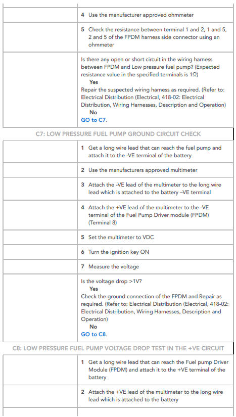
PINPOINT TESTS
NOTE:
Two ohmmeters are required for this test.
NOTE:
If the measurement range of the ohmmeter is set to 'automatic', the ohmmeter will briefly display 'open circuit' when the range changes.
This does not indicate a fault with the component. To prevent incorrect diagnosis, always set the measurement range to 'manual'.
NOTE:
This test should be carried out by turning the ignition ON.
WARNING:
This procedure involves fuel handling. Be prepared for fuel spillage at all times and always observe fuel handling precautions. Failure to follow these instructions may result in personal injury
NOTE:
This procedure involves disconnection of fuel lines. Place suitable absorbent material around the fuel line to be disconnected, to absorb any spillage when connecting the fuel pressure gauge.
NOTE:
This procedure involves disconnection of fuel lines. Place suitable absorbent material around the fuel line to be disconnected, to absorb any spillage when connecting the fuel pressure gauge.
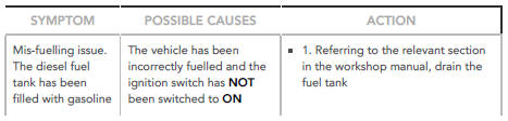
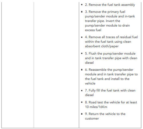
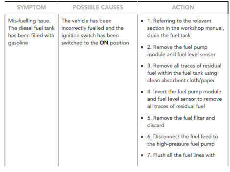
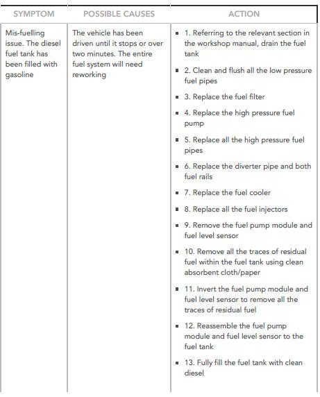
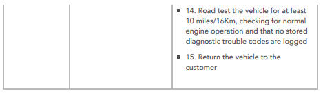
MIS - FUELLING ISSUES / ACCIDENTALLY FILLING THE FUEL TANK WITH GASOLINE INSTEAD OF DIESEL
NOTES:
- The customer MUST be informed prior to vehicle hand-over of the consequences of adding gasoline to the fuel tank instead of diesel.
- The cost of this repair work is not Jaguar Land Rover's responsibility. If the customer does not have all of the appropriate work carried out, warranty may be refused on all affected components.
- If the customer refuses the advised repair or wants a lower level repair than advised, the vehicle must be added to the Restricted Warranty Register.
- Vehicle mis-fuelling will not result in a formal warranty restriction if the approved repair has been completed.
- The symptom charts below describe the four possible scenarios of a customer incorrectly fuelling a diesel engine vehicle with gasoline. When customers report a mis-fuel, allow them to fully explain exactly what took place before advising the necessary repair.
- The procedures listed below are for guidance only. The relevant sections of TOPIx must be referred to for all detailed procedures and replacement of parts.
- Purge operation of the low pressure fuel pumps on the following vehicle lines is activated when the drivers door is opened: Jaguar XE, Jaguar XF, Jaguar F-Pace. For all other vehicle lines, the purge operation of the low pressure fuel pumps is activated when the ignition is switched on.
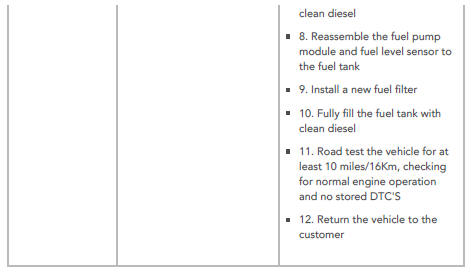
Mis-fuelling Procedure 1
Mis-fuelling Procedure 2
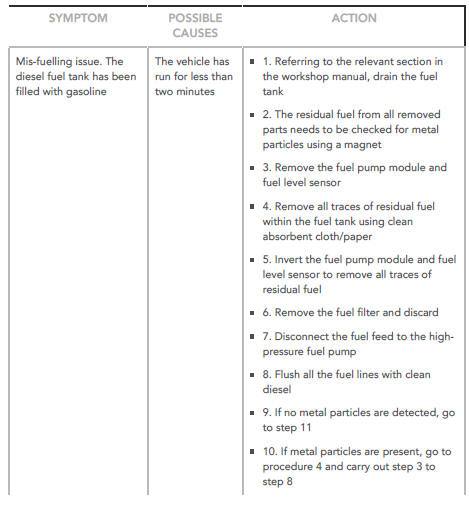
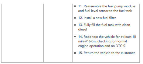
Mis-fuelling Procedure 3
Mis-fuelling Procedure 4
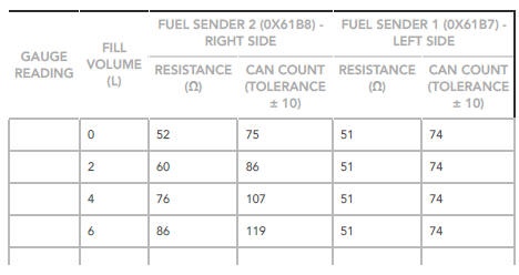
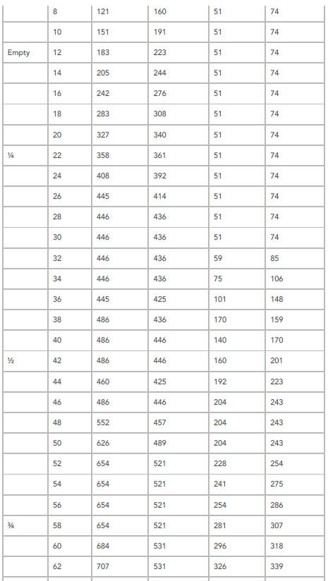
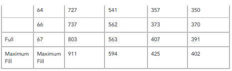
FUEL GAUGE , RESISTANCE , VOLTAGE AND FUEL TANK LEVEL COMPARISON CHART
Use the chart to determine fuel tank fuel volume versus fuel gauge reading to determine the fuel level symptom and fault.
NOTES:
- The vehicle must be parked on a level surface to obtain an accurate fuel level gauge reading.
- The actual values may vary, according to the quantity of fuel in the left and right sides of the fuel tank.
- An accurate fuel level gauge reading requires 3 to 5 minutes for levels to stabilise.
Volume, Resistance and Voltage Values
DTC INDEX
For a list of Diagnostic Trouble Codes (DTCs) that could be logged on this vehicle, please refer to Section 100-00. Diagnostic Trouble Code (DTC Index - INGENIUM I4 2.0L Diesel, DTC: Engine Control Module (ECM) B10A2-07 to P034B-76
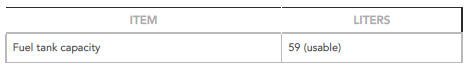
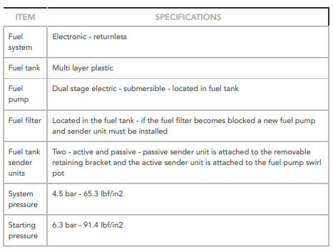
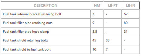
Fuel Tank and Lines - Ingenium i4 2.0l Diesel Specifications
Capacity
General Specifications
Torque Specifications
READ NEXT:
 Fuel Tank Draining (G898063) / General Procedures
WARNINGS:
Place the vehicle in a well ventilated, quarantined area and
arrange
' No Smoking/Petrol Fumes' signs about the vehicle.
Do not carry or operate cellular phones when working on or near
Clutch / Description and Operation
COMPONENT LOCATION
Clutch pedal
Brake/clutch reservoir
Brake fluid level sensor
High pressure clutch line
Clutch master cylinder
Clutch pedal position sensor
Low pressure hose connector
Low
SEE MORE:
Engine Cooling - Ingenium i4 2.0l Diesel / Description and Operation
COMPONENT LOCATION
Expansion tank
Coolant pump
Oil cooler
Fuel cooler
Heater hoses
Exhaust Gas Recirculation (EGR)
Exhaust Gas Recirculation (EGR) cooler
Charger air cooler
Transmission fluid cooler
Cooling fan
Thermostat
Coolant pump - electronic
OVERVIEW
The engine cooling system m
Manual Transmission Transaxle
External Controls
Gearshift Cables (G1779360)
/ Removal and Installation
REMOVAL
NOTES:
Removal steps in this procedure may contain installation details.
Some variation in the illustrations may occur, but the essential
information is always correct.
Refer to: Air Cleaner (303-12, Removal and Installation).
NOTE:
Neutral must be selected before the cables are release
