Land Rover Discovery: Fuse box locations
.jpg)
When a fuse box lid is removed, take care to protect the box from moisture, and refit the lid at the earliest opportunity.
Access can be gained to the fuses, as follows:
- Engine compartment fuse box.
- To gain access to the fuse box: Remove the 2 plastic fixings (see illustration) and pull the tube up to release it from the air box.
- Unlatch the tabs (arrowed) to
release the fuse box cover.
The engine compartment fuse numbers and positions are shown on the inside of the fuse box cover.
- Passenger compartment fuse box (upper): Open the glovebox and remove the panel from the glovebox liner. A label on the panel shows the circuits protected and the fuse locations.
- Passenger compartment fuse box (lower): Remove the lower access panel.
- Luggage compartment (loadspace) fuse boxes: Rotate the latch and remove the panel from the left side trim of the luggage compartment. A label on the panel shows the circuits protected and the fuse locations.
CHANGING A FUSE
- Always switch off the ignition system, and the affected electrical circuit, before replacing a fuse.
- Fit Land Rover approved replacement fuses of the same rating and type, or fuses of a matching specification. Using an incorrect fuse, may result in damage to the vehicle's electrical system and can result in a fire.
- If the replacement fuse blows after fitment, the system should be checked by your Retailer/ Authorised Repairer.
Note: It is recommended that relays should only be renewed by qualified persons.
The fuse removal tweezers are located in the passenger compartment fuse box.
Press the tweezers onto the head of a fuse and pull to remove. A break in the wire inside the fuse indicates that the fuse has blown and must be renewed.
There are some spare replacement fuses in the passenger compartment fuse box.
See the fuse box label for details.
ENGINE COMPARTMENT FUSE BOX
.jpg)
.jpg)
*It is recommended that these fuses should only be serviced by a Retailer/ Authorised Repairer.
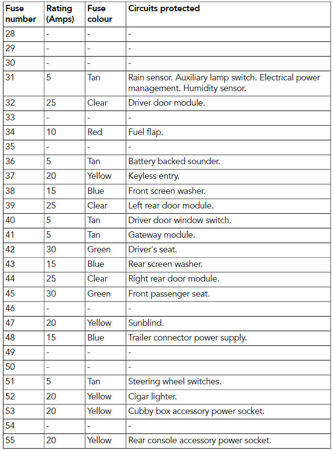
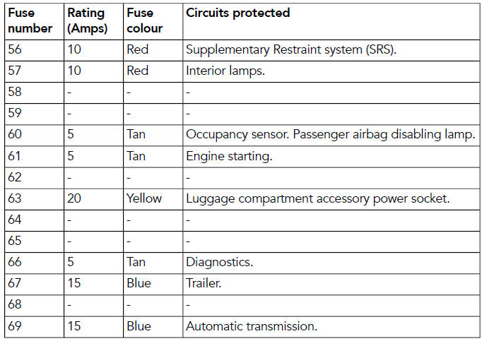
PASSENGER COMPARTMENT FUSE BOX
.jpg)
READ NEXT:
 Luggage compartment fuse box
Fuse box 1
Fuse box 2
Fuse box 3
Fuse box 4
Fuse box 1
Fuse box 2
Fuse box 3
Fuse box 4
Tyre markings
P indicates that the tyre is for
passenger vehicle use. This index is
not always shown.
The width of the tyre from sidewall
edge to sidewall edge, in millimetres.
The aspect ratio, also known
SEE MORE:
Brake Hydraulics
Always observe the following recommendations when working on the
braking system:
WARNING:
Do not intermix brake fluid of different specifications.
Always use two spanners when loosening or tightening brake pipes or
hose connections.
Make sure that hoses run in a natural curve and are not kinked
Glass Roof Panel (G1805062) - Removal
Removal
Refer to: Glass Roof Panel Blind (501-11, Removal and Installation).
CAUTIONS:
Protect the surrounding paintwork to avoid damage.
Protect the surrounding components.
WARNING:
Wear safety goggles and protective gloves.
CAUTIONS:
The glass roof panel adhesive is uneven as there are
