Land Rover Discovery: Parking Brake and Actuation Parking Brake Release Actuator (G1785118) / Removal and Installation
PART(S)
.jpg)
REMOVAL
NOTE:
Removal steps in this procedure may contain installation details.
Connect the diagnostic tool and set the electric park brake (EPB) to the maintenance position.
NOTE:
This step is only required if the diagnostic tool is not available.
Refer to: Electronic Parking Brake Service Mode Activation and Deactivation (206-05 Parking Brake and Actuation, General Procedures).
NOTE:
This step is only required if the vehicle has no battery power.
Refer to: Electronic Parking Brake Release When the Vehicle Has No Electrical Power (206-05 Parking Brake and Actuation, General Procedures).
WARNING:
Make sure to support the vehicle with axle stands.
Raise and support the vehicle.
Refer to: Wheel and Tire (204-04 Wheels and Tires, Removal and Installation).
NOTE:
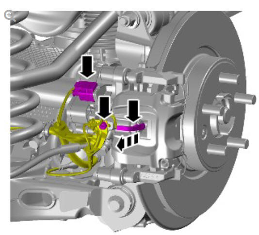
Remove and discard the O-ring seal.
.jpg)
Renew Part: Electric park brake actuator O-ring seal.
Torque: 11 Nm
INSTALLATION
CAUTION:
A new O-ring seal is to be installed.
To install, reverse the removal procedure
Calibrate the EPB using the diagnostic tool.
NOTE:
This step is only required if the diagnostic tool is not available.
Refer to: Electronic Parking Brake Service Mode Activation and Deactivation (206-05 Parking Brake and Actuation, General Procedures).
NOTE:
This step is only required if the vehicle has no battery power.
Refer to: Electronic Parking Brake Release When the Vehicle Has No Electrical Power (206-05 Parking Brake and Actuation, General Procedures).
Parking brake and actuation parking brake switch (G1785119) removal and installation
REMOVAL
NOTE:
Removal steps in this procedure may contain installation details.
All vehicles
- Disconnect the battery ground cable.
Refer to: Specifications (414-01 Battery, Mounting and Cables, Specifications).
.jpg)
Vehicles with manual transmission
WARNING:
The selector lever knob will be released suddenly, keep face clear during removal.
.jpg)
.jpg)
Vehicles with automatic transmission
.jpg)
All vehicles
.jpg)
Torque: 1.1 Nm
INSTALLATION
- To install, reverse the removal procedure.
READ NEXT:
 Parking Brake and Actuation / Description and Operation
COMPONENT LOCATION
NOTE:
Right Hand Drive (RHD) illustration shown, Left Hand Drive (LHD)
illustration similar
Integrated Anti-lock Brake System (ABS) control module and Hydraulic
Control
Unit
Clutch Pedal Position Sensor (Manual Ransmission Vehicles Only)
The clutch pedal position sensor provides the ABS control module with a
continuous measure of clutch pedal position.
The clutch pedal position sensor is attached to the clutch master cylinder.
The
Parking Brake and Actuation - Operation
Operation
When the park brake is applied with the EPB switch, the ABS control
module uses the wheel speed inputs to determine when to use the static
and dynamic modes of operation. It uses the static
SEE MORE:
Oil Pan
Flange bolt
Sprocket
Variable flow oil pump with integral vacuum pump
Oil level gauge
Oil level gauge tube
Bolt (4 off)
Oil pan
Bolt (16 off)
Sealing washer
Drain plug
The oil pan is cast from aluminum alloy using a high pressure die cast
process and is located on the underside of the c
Sectioned View of Typical
Fuel Fired
Booster Heater
Combustion air fan
Coolant inlet
Coolant outlet
Burner insert
Heat exchanger
Overheat temperature sensor
Exhaust
Fuel inlet
Evaporator
Air inlet
COMBUSTION AIR FAN
The combustion air fan regulates the flow of air into the FFBH to support
combustion of the fuel supplied by the FFBH fuel
