Land Rover Discovery: Rear Suspension Wheel Knuckle (G1775239) / Installation
INSTALLATION
CAUTION:
Install a new and bolt.
NOTE:
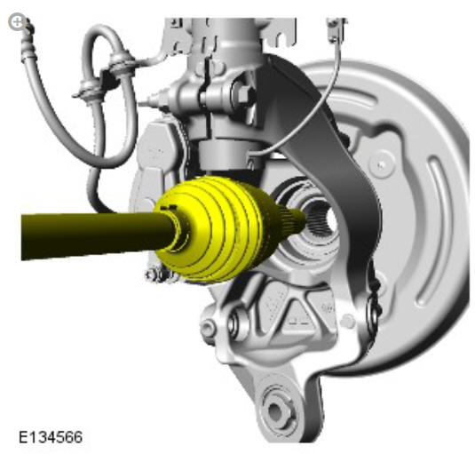
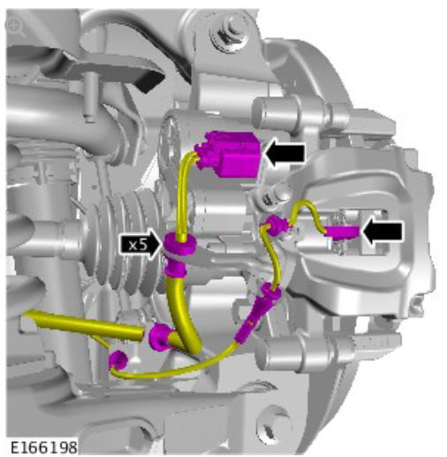
All wheel drive transmission illustrations shown, front wheel drive transmission is similar.
Renew Part: Wheel knuckle nut and bolt.
Torque:
Stage 1: 40 Nm
Stage 2: 180º
CAUTIONS:
- Pull on the halfshaft inboard joint to make sure the clip has fully engaged and retains the halfshaft inboard joint within the differential case.
- Keep the halfshaft horizontal to avoid damaging the oil seal.
NOTE:
Do not fully engage the halfshaft into the axle assembly until the oil seal protector has been removed.
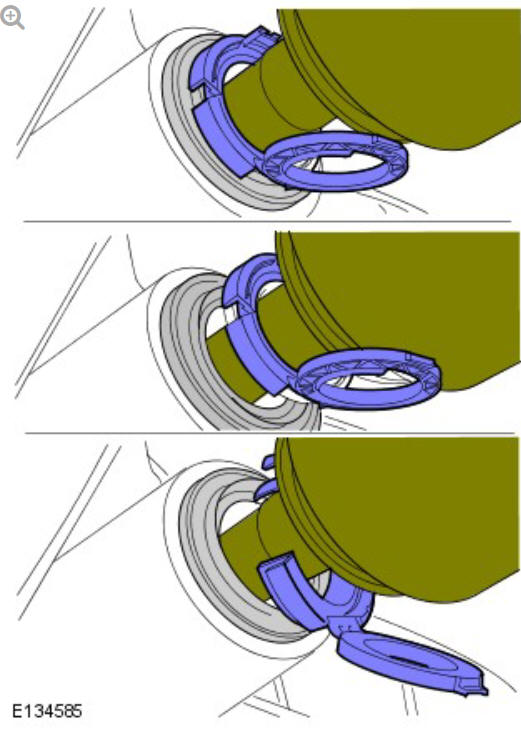
Make sure the snap ring is fully engaged and retains the halfshaft.
CAUTION:
Install a new nut and bolt.
Renew Part: Wheel knuckle nut and bolt.
Torque:
Stage 1: 40 Nm
Stage 2: 180º
CAUTION:
Install a new nut and bolt.
Renew Part: Wheel knuckle nut and bolt.
Torque:
Stage 1: 40 Nm
Stage 2: 180º
CAUTION:
Install new nuts and bolts.
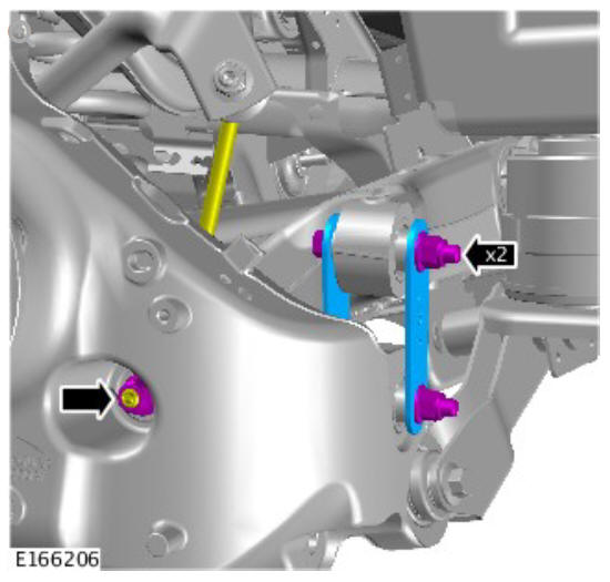
Renew Part: lower control arm nut(s) and bolt(s).
Torque:
Stabiliser bar link 56 Nm
Integral link
Stage 1: 40 Nm
Stage 2: 180º
CAUTION:
Install new nuts.
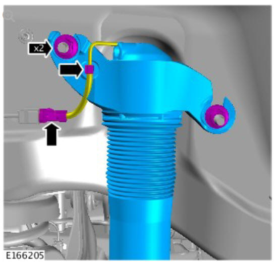
Renew Part: Shock absorber upper mounting nuts.
Torque: 80 Nm
Refer to: Rear Wheel Arch Liner (501-08 Exterior Trim and Ornamentation, Removal and Installation).
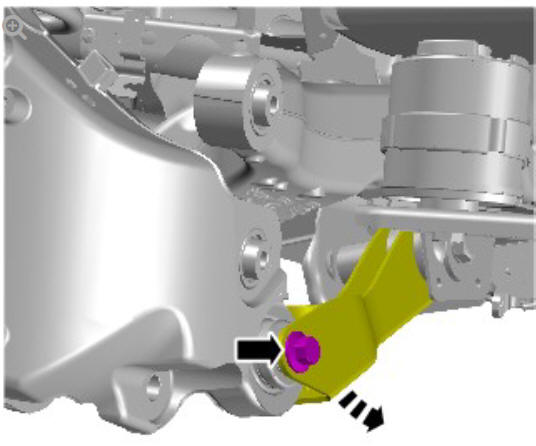
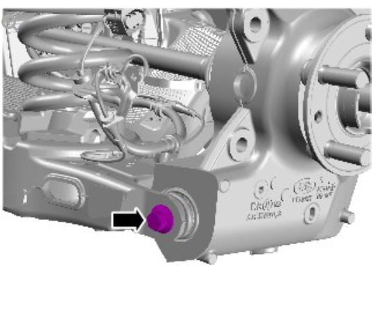
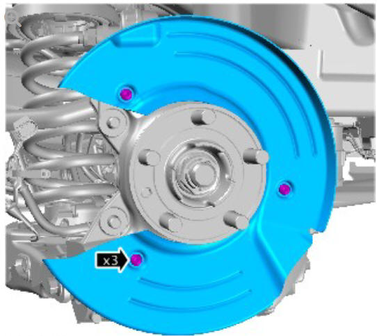
CAUTION:
Install new bolt.
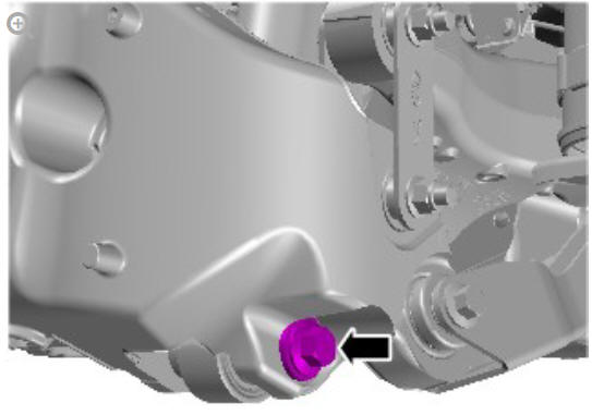
Renew Part: Wheel knuckle bolt(s).
Torque: 170 Nm
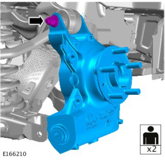
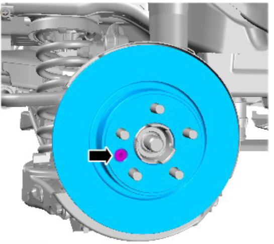
CAUTION:
Make sure the height sensor arm is pointing outwards
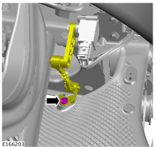
Torque: 10 Nm

Torque: 9 Nm
NOTE:
All wheel drive transmission illustrations shown, front wheel drive transmission is similar.
Torque: 9 Nm
NOTE:
All wheel drive transmission illustrations shown, front wheel drive transmission is similar.
Torque: 35 Nm
CAUTIONS:
- Install new bolts.
- Make sure that the brake hose is not twisted and is correctly located.
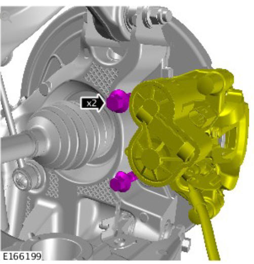
Renew Part: Brake caliper carrier bolts.
Torque:
Stage 1: 70 Nm
Stage 2: 120º
CAUTIONS:
- Install the retained nut.
- Do not use air tools to install the nut. Failure to follow this instruction may result in damage to the component.
- Tighten the nut without the weight of the vehicle on the suspension.
Torque: 175 Nm
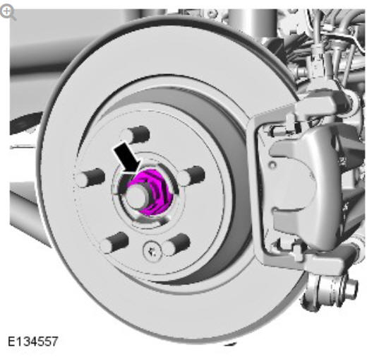
Remove and discard the halfshaft retaining nut.
WARNING:
Install a new nut.
CAUTIONS:
- Do not use air tools to install the nut. Failure to follow this instruction may result in damage to the component.
- Tighten the nut without the weight of the vehicle on the suspension.
Renew Part: Rear halfshaft nut.
Torque: Stage 1: 100 Nm
Stage 2: 90º
Refer to: Wheel and Tire (204-04 Wheels and Tires, Removal and Installation).
Calibrate the electric parking brake (EPB) using the diagnostic tool.
Depress the brake pedal several times, check the fluid level in the brake fluid reservoir and top-up with brake fluid if necessary.
Check and if necessary, adjust the rear wheel alignment
READ NEXT:
 Rear Suspension / Description and Operation
COMPONENT LOCATION
Shock absorber
Spring
Stabilizer bar
Wheel knuckle
Tie arm
Lower control arm
Subframe
Stabilizer bar link
OVERVIEW
An advanced multi-link rear suspension is introduced pr
Spring and Shock Absorber
NOTE:
Adaptive dynamics damper shown, standard damper similar.
Bolt - shock absorber to wheel knuckle
Shock absorber
Nut - Shock absorber top mounting to body fastener
Nut - shock absorber to t
Lower Control Arm and
Tie Bar
Flag nut retaining screw
Flag nut - lower control arm to wheel knuckle
Bush - lower control arm to wheel knuckle
Bolt - lower control arm to wheel knuckle
Lower control arm
Bolt (front) - low
SEE MORE:
Front Suspension Front
Shock Absorber (G1779642) - Removal
GENERAL EQUIPMENT
PART(S)
REMOVAL
WARNINGS:
Make sure the spring compressor Safe Working Load (SWL) meets
or exceeds the spring rating quoted in the Specifcations section.
Always follow the spring compressor manufacturer's
instructions.
The spring is under extreme tension, care must be tak
Using the seat belts
Putting on a seat belt: Draw the belt
out smoothly, making sure that the
seat position and your position on the
seat are correct.
When correctly positioned, the seat
belt should cross the collar bone at the
mid-point between the neck and the
end of your shoulder.
Where possible, rear se
