Land Rover Discovery: Wipers and Washers / Diagnosis and Testing
PRINCIPLES OF OPERATION
For a detailed description of the Wipers and Washers system, refer to the relevant Description and Operation section in the workshop manual. REFER to: Wipers and Washers (501-16 Wipers and Washers, Description and Operation).
INSPECTION AND VERIFICATION
CAUTION:
Diagnosis by substitution from a donor vehicle is NOT acceptable.
Substitution of control modules does not guarantee confirmation of a fault, and may also cause additional faults in the vehicle being tested and/or the donor vehicle.
NOTES:
- If a control module or a component is suspect and the vehicle remains under manufacturer warranty, refer to the Warranty Policy and Procedures manual, or determine if any prior approval programme is in operation, prior to the installation of a new module/component.
- When performing voltage or resistance tests, always use a digital multimeter accurate to three decimal places, and with an up-todate calibration certificate. When testing resistance always take the resistance of the digital multimeter leads into account.
- Check and rectify basic faults before beginning diagnostic routines involving pinpoint tests.
- Verify the customer concern
- Visually inspect for obvious signs of damage and system integrity
Visual Inspection
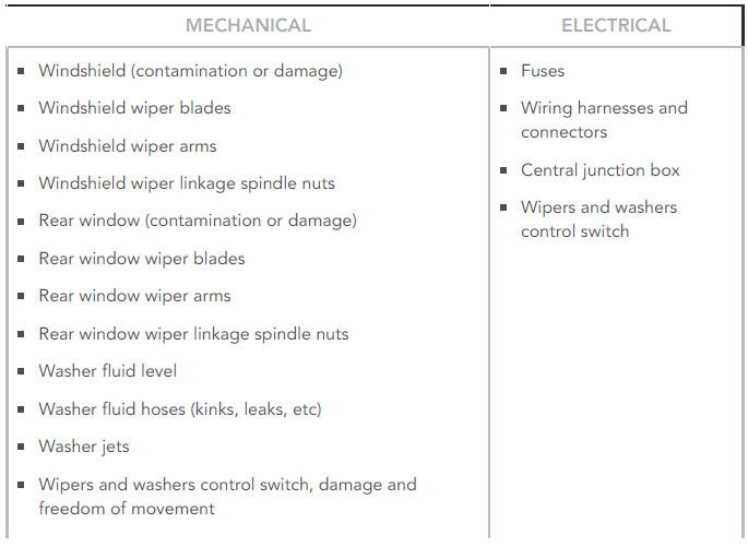
- If an obvious cause for an observed or reported concern is found, correct the cause (if possible) before proceeding to the next step
- If the cause is not visually evident, verify the symptom and refer to the Symptom Chart, alternatively check for Diagnostic Trouble Codes (DTCs) and refer to the DTC Index
- Check DDW for open campaigns. Refer to the corresponding bulletins and SSMs which may be valid for the specific customer complaint and carry out the recommendations as required
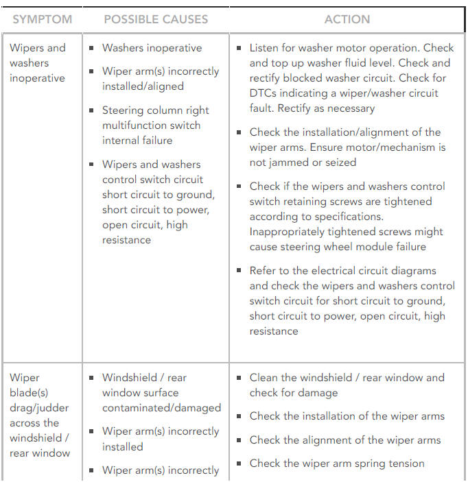
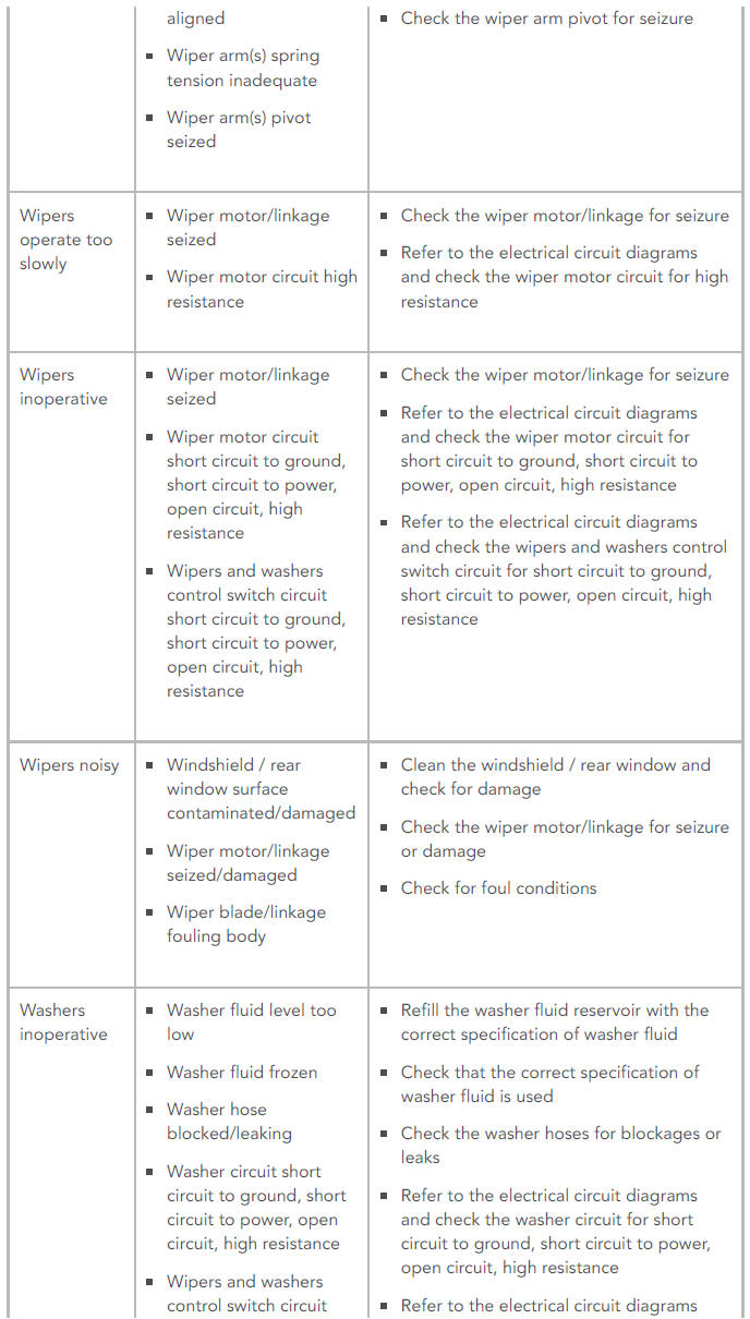
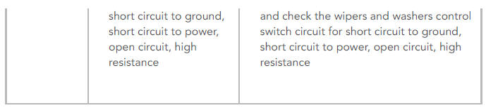
SYMPTOM CHART
DTC INDEX
For a list of Diagnostic Trouble Codes (DTCs) that could be logged on this vehicle, please refer to Section 100-00. REFER to: Diagnostic Trouble Code Index - DTC: Central Junction Box (CJB) (100-00 General Information, Description and Operation).
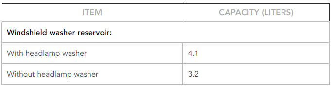
Wipers and washers specifications
Capacities
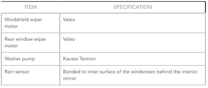
General Specification
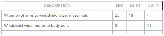
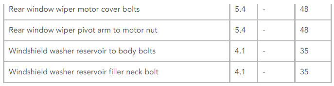
Torque Specifications
READ NEXT:
 Anti-lock Control Anti-lock Brake System Module (G1807249) / Removal and
Installation
Anti-lock Control Anti-lock Brake System Module (G1807249) / Removal and
Installation
REMOVAL
CAUTIONS:
If brake fluid is spilt on the paintwork, the affected area must
be
immediately washed down with cold water.
Make sure that all openings are sealed. Use new blanking caps.
NOT
SEE MORE:
Exhaust - Ingenium i4 2.0l Diesel Exhaust System DTC- Selective Catalytic
Reduction (SCR) / Diagnosis and Testing
PRINCIPLE OF OPERATION
For a detailed description of the Exhaust System, refer to the relevant
Description and Operation section of the workshop manual.
REFER to: Selective Catalyst Reduction (309-00C Exhaust System -
INGENIUM I4 2.0L Diesel, Description and Operation)
INSPECTION AND VERIFICATION
C
Recovery method
The method for recovery/transportation
of the vehicle is on a transporter or trailer
designed for that purpose.
Make sure that vehicle recovery/
transportation is carried out by
suitably qualified personnel and the
vehicle is secured correctly.
The recovery agent must activate
the Transmissio
