Land Rover Discovery: Anti-lock Control Anti-lock Brake System Module (G1807249) / Removal and Installation
Land Rover Discovery (2009–2016) Service Manual / Chassis / Chassis-Brake-System / Anti-lock Control Anti-lock Brake System Module (G1807249) / Removal and
Installation
REMOVAL
CAUTIONS:
- If brake fluid is spilt on the paintwork, the affected area must be immediately washed down with cold water.
- Make sure that all openings are sealed. Use new blanking caps.
NOTES:
- Removal steps in this procedure may contain installation details.
- LHD illustration shown, RHD is similar.
All vehicles
WARNING:
Make sure to support the vehicle with axle stands.
Raise and support the vehicle.
Refer to: Plenum Chamber (412-01 Climate Control, Removal and Installation).
Refer to: Battery Tray (414-01 Battery, Mounting and Cables, Removal and Installation).
Vehicles with petrol engine
Vehicles with diesel engine
All vehicles
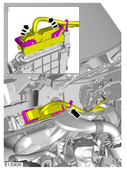
NOTE:
Component shown removed for clarity.
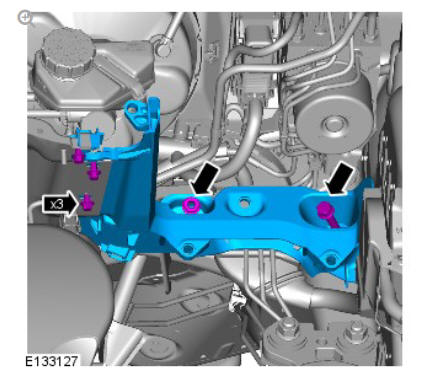
Torque: 17 Nm
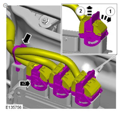
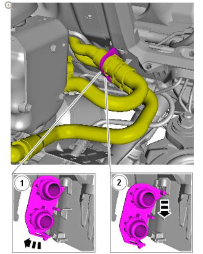
WARNING:
Fluid loss is unavoidable, use absorbent cloth or a container to collect the fluid.
Torque: 17 Nm
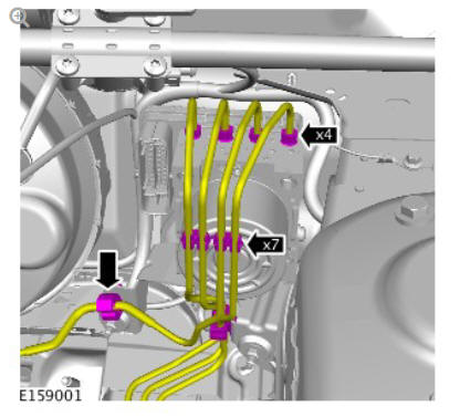
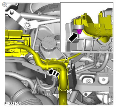
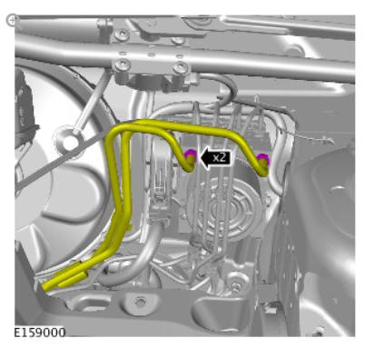
Torque: 14 Nm
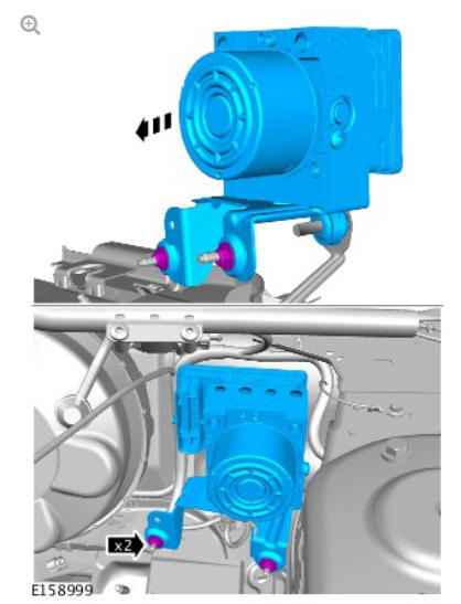
Torque: 9 Nm
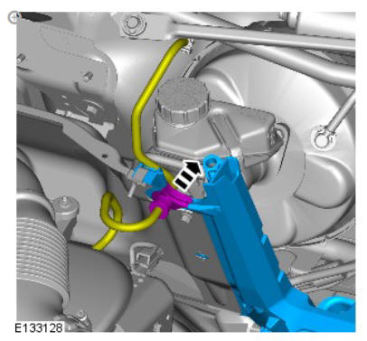
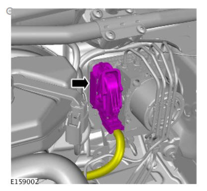
NOTE:
Do not disassemble further if the component is removed for access only.
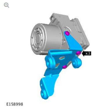
Torque: 9 Nm
INSTALLATION
NOTE:
Remove and discard all blanking caps.
- To install, reverse the removal procedure.
- Refer to: Brake System Pressure Bleeding (206-00 Brake System - General Information, General Procedures).
- If a new component has been installed, configure using Land Rover approved diagnostic equipment.
READ NEXT:
 Anti-lock Control Front Wheel Speed Sensor (G1807250) / Removal and
Installation
Anti-lock Control Front Wheel Speed Sensor (G1807250) / Removal and
Installation
REMOVAL
NOTE:
Removal steps in this procedure may contain installation details.
WARNING:
Make sure to support the vehicle with axle stands.
Raise and support the vehicle.
Refer to: Fender Splash Shiel
Anti-lock Control - Traction Control / Description and Operation
COMPONENT LOCATION - SHEET1 OF 2
NOTE:
Right Hand Drive (RHD) illustration shown, Left Hand Drive (LHD)
illustration similar
Rear right wheel speed sensor
Rear left wheel speed sensor
Front righ
Dynamic Stability Control (DSC) Switch
DESCRIPTION
The Dynamic Stability Control (DSC) switch is a non-latching switch installed
in the floor console, forward of the selector lever (for manual transmission
vehicles) or Transmission Contr
SEE MORE:
Exterior Lighting Front Fog Lamp Adjustment
NOTES:
Some variation in the illustrations may occur, but the essential
information is always correct.
Left illustration shown, Right is similar.
NOTE:
The fog lamp beam should be set at 2% below the horizontal
and parallel.
Check the fog lamp beam alignment.
Align the beam setting equipment to
Exterior Trim and Ornamentation
Front Door
Lower Moulding (G1796376)
/ Removal and Installation
PART(S)
REMOVAL
CAUTION:
Make sure to protect the paintwork.
NOTES:
Removal steps in this procedure may contain installation details.
RH illustration shown, LH is similar.
CAUTION:
Do not use tools during this operation, removal of the
component(s) must be carried out by hand.
NOTE:
Discard th
© 2019-2026 Copyright www.lrdisc.com
