Land Rover Discovery: Dynamic Stability Control (DSC) Switch
DESCRIPTION
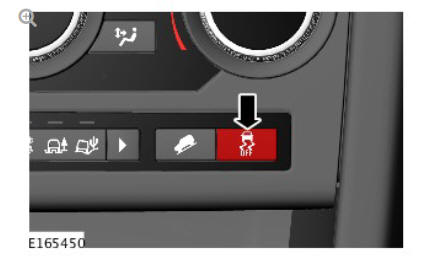
The Dynamic Stability Control (DSC) switch is a non-latching switch installed in the floor console, forward of the selector lever (for manual transmission vehicles) or Transmission Control Switch (for automatic transmission vehicles). Pressing the DSC switch connects an ignition power supply to the Anti-lock Brake System (ABS) control module. With the first press of the DSC switch, the ABS control module disables the DSC functions. When the DSC switch is pressed again, the ABS control module re-enables the DSC functions. The DSC switch must be pressed for a minimum of 0.3 second for the ABS control module to react. The DSC function is re-enabled at the beginning of each ignition cycle. To confirm that the DSC function is selected off, the amber colored DSC OFF warning indicator in the Instrument Cluster (IC) is continuously illuminated. A message is also displayed in the message center to confirm that DSC is selected off. When the DSC function is selected on again, the DSC OFF warning indicator and message go off.
Although Land Rover recommend that DSC is selected on for all normal driving conditions, it may be beneficial to deselect DSC in order to maximize traction under the following conditions:
- To rock the vehicle out of a hollow or a soft surface.
- When driving on loose surfaces or with snow chains installed.
- When driving in deep sand, snow or mud.
- When driving on tracks with deep longitudinal ruts.
To prevent mis-use of, or in the event of a broken DSC switch, a Diagnostic Trouble Code (DTC) is stored in the ABS control module memory if the input from the DSC switch is held high for more than 1 minute.
HILL DESCENT CONTROL (HDC) SWITCH
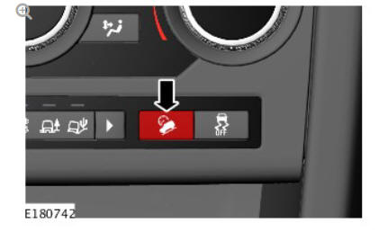
The Hill Descent Control (HDC) switch controls the selection of the HDC function.
The HDC switch is a non-latching switch installed in the floor console.
Momentarily pressing and releasing the HDC switch connects an ignition power supply to the Anti-lock Brake System (ABS) control module. With the first press and release of the HDC switch, the ABS control module enables operation of the HDC function. When the HDC switch is pressed and released again, the ABS control module disables operation of the HDC function.
To prevent mis-use of, or in the event of a broken HDC switch, if the switch is pressed for more than 10 seconds no change of state occurs. A Diagnostic Trouble Code (DTC) is stored in the ABS control module memory if the input from the HDC switch is held high for more than 1 minute.
HILL DESCENT CONTROL (HDC) AND ALL TERRAIN PROGRESS CONTROL (ATPC) SWITCH
The Hill Descent Control (HDC) and All Terrain Progress Control (ATPC) switch controls the selection of the HDC and ATPC function.
The HDC/ATPC switch is a non-latching switch installed in the floor console.
Momentarily pressing and releasing the HDC/ATPC switch connects an ignition power supply to the Anti-lock Brake System (ABS) control module.
With the first press and release of the HDC/ATPC switch, the ABS control module enables operation of the ATPC function.
With the second press and release of the HDC/ATPC switch within 4 seconds of the first press, the ABS control module enables operation of the HDC function. If the second press and release is more than 4 seconds after the first press, the ABS control module disables operation the ATPC function.
The ATPC/HDC switch cycles between enable ATPC function, enable HDC function (if within 4 seconds of previous press) and disable active function (HDC or ATPC).
To prevent mis-use of, or in the event of a broken HDC/ATPC switch, if the switch is pressed for more than 10 seconds no change of state occurs. A Diagnostic Trouble Code (DTC) is stored in the ABS control module memory if the input from the HDC/ATPC switch is held high for more than 1 minute.
READ NEXT:
 Wheel Speed Sensors
Retaining screw
Wheel speed sensor
Bearing seal and magnetic encoder ring
Wheel bearing
Wheel hub
An active wheel speed sensor is installed in each wheel knuckle, and
provides the Anti-lock B
Steering Angle Sensor
The steering angle sensor is integrated into the clockspring.
The clockspring is mounted to the upper steering column with two screws,
and receives an electrical supply from the main harness via a
Anti-lock Brake System (ABC) Control Module
Anti-lock Brake System (ABS) control module
Hydraulic Control Unit (HCU)
The Anti-lock Brake System (ABS) control module controls the brake
functions by operating the Hydraulic Control Unit (HCU
SEE MORE:
Instrument panel menu
A number of vehicle features and display
settings may be configured via the
Instrument panel menu.
To display and navigate through the
Instrument panel menu, operate the menu
control on the steering wheel.
Steering wheel menu control: Press to
activate the menu, then use as follows:
Press t
Seating - Operation
FRONT SEAT ADJUSTMENT - NON-MEMORY SEATS
The driver and passenger seat switchpacks each receive a permanent fused
primary battery power supply from the Central Junction Box (CJB). This
feed is always live regardless of ignition power mode status.
Each switch provides a ground and power supply to th
