Land Rover Discovery: Steering Angle Sensor
The steering angle sensor is integrated into the clockspring.
The clockspring is mounted to the upper steering column with two screws, and receives an electrical supply from the main harness via a multi-pin connector located on the side of the unit. The module provides the location and electrical connection for the two multifunction switches.
Input signals from the steering angle sensor are received and processed by the clockspring to calculate the steering wheel angle, and steering wheel angle speed. The information, together with signal integrity information, is transmitted on the High Speed (HS) Controller Area (CAN) chassis bus for use by the Anti-lock Brake System (ABS) control module and functions such as Dynamic Stability Control (DSC).
A code wheel and 16 optical digital sensors are installed inside the steering angle sensor. Rotation of the code wheel is read by the optical digital sensors to produce steering wheel rotational speed signals. The steering angle sensor is able to measure a rotation range of +/-720 degrees, although the steering mechanism will only allow the steering wheel to rotate a maximum of +/-540 degrees.
If a fault occurs within the steering angle sensor, a Diagnostic Trouble Code (DTC) will be set and stored in the steering angle sensor memory. The steering angle sensor fault is also stored in the ABS control module memory.
The ABS control module will also illuminates the appropriate warning indicators, depending on the brake functions affected. A warning chime is also sounded to alert the driver to the fault condition and, if the fault affects the HDC or ATPC function, a message is displayed in the message center.
The steering angle sensor and ABS control module can be interrogated using Land Rover approved diagnostic equipment.
BRAKE WARNING INDICATORS
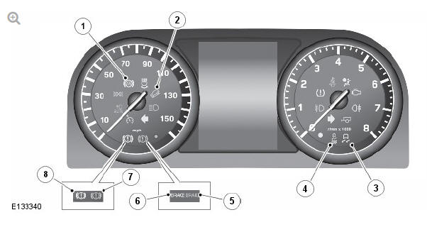
- Anti-lock Brake System (ABS) warning indicator
- Hill Descent Control (HDC) active indicator
- Dynamic Stability Control (DSC) warning indicator
- DSC OFF warning indicator
- Brake red warning indicator (North American Specification (NAS) vehicles only)
- Brake amber warning indicator (NAS vehicles only)
- Brake red warning indicator (Rest of World (ROW) vehicles only)
- Brake amber warning indicator (ROW vehicles only)
The Instrument Cluster (IC) contains various warning indicators for the antilock control - traction control functions. The warning indicators provide a visual indication of either a system fault or system operating status.
READ NEXT:
 Anti-lock Brake System (ABC) Control Module
Anti-lock Brake System (ABS) control module
Hydraulic Control Unit (HCU)
The Anti-lock Brake System (ABS) control module controls the brake
functions by operating the Hydraulic Control Unit (HCU
Anti-lock Control - Operation
ANTI-LOCK BRAKE SYSTEM (ABS)
The Anti-lock Brake System (ABS) controls the speed of all road wheels to
ensure optimum wheel slip when braking at the adhesion limit. The wheels
are prevented from locki
Anti-lock Control - Traction Control / Diagnosis and Testing
PRINCIPLES OF OPERATION
For a detailed description of the Anti-lock Brake System, refer to the
relevant Description and Operation section in the workshop manual. REFER
to: Anti-Lock Control - Traction
SEE MORE:
Rear Suspension Rear
Wheel Bearing (G1818219)
/ Removal and Installation
SPECIAL TOOL(S)
GENERAL EQUIPMENT
REMOVAL
NOTES:
Some variation in the illustrations may occur, but the essential
information is always correct.
Some components shown removed for clarity.
WARNING:
Do not work on or under a vehicle supported only by a jack.
Always support the vehicle on s
Rear Drive Axle - Differential - Vehicles with- Active Driveline Drive Pinion
Seal (G1781297) - Installation
Installation
CAUTION:
Make sure new bolts are installed.
Renew Part: Differential case rear bolts.
Refer to: Fuel Tank (310-01A Fuel Tank and Lines - TD4 2.2L Diesel,
Removal and Installation).
Refer to: Fuel Tank (310-01A Fuel Tank and Lines - TD4 2.2L Diesel,
Removal and Installation).
CA
