Land Rover Discovery: Wheel Speed Sensors
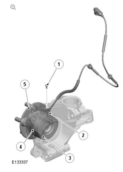
- Retaining screw
- Wheel speed sensor
- Bearing seal and magnetic encoder ring
- Wheel bearing
- Wheel hub
An active wheel speed sensor is installed in each wheel knuckle, and provides the Anti-lock Brake System (ABS) control module with a rotational speed signal from each road wheel. The head of each wheel speed sensor is positioned close to a magnetic encoder incorporated into the seal of the wheel bearing. Each front axle bearing encoder contains 48 north and south pole pairs; each rear axle bearing encoder contains 48 pole pairs. A fly lead connects each sensor to the vehicle harness.
The wheel speed sensor is supplied with a power supply and a signal connection from the ABS control module. When the ignition switch is in power mode 6 (ignition), the ABS control module supplies power to the wheel speed sensors and monitors the return signals. Rotation of the wheels induces current fluctuations in the speed sensor return signals. The ABS control module subsequently converts the return signals into individual wheel speeds and the overall vehicle speed.
The ABS control module outputs the individual wheel speeds and the overall vehicle speed on the High Speed (HS) Controller Area Network (CAN) chassis bus for use by other systems. The quality of the vehicle speed signal is also broadcast on the HS CAN chassis bus. If all wheel speed signals are available to calculate vehicle speed from, the quality of the vehicle speed signal is set to 'data calculated within specified accuracy'. If one or more wheel speed sensors are inoperative, the quality of the vehicle speed signal is set to 'accuracy outside specification'.
The ABS control module monitors the wheel speed sensor circuits for faults.
If a fault is detected the ABS control module stores a related Diagnostic Trouble Code (DTC) in memory and illuminates the appropriate brake warning indicators, depending on the system functions affected. A warning chime is also sounded to alert the driver to the fault condition and, if the fault affects the Hill Descent Control (HDC) or All Terrain Progress Control (ATPC) function, a message is displayed in the Instrument Cluster (IC) message center.
As the wheel speed sensors are active devices, a return signal is available when the road wheels are not rotating. This enables the ABS control module to check the condition of the speed sensors while the vehicle is stationary.
RESTRAINTS CONTROL MODULE (RCM)
The yaw rate lateral acceleration sensor is located within the Restraints Control Module (RCM). The RCM is located under the front of the floor console. The RCM is secured by three nuts and connects to the vehicle wiring via a multi-pin connector.
When the ignition is on, the yaw rate lateral acceleration sensor within the RCM receives a power supply from the Central Junction Box (CJB). The sensor measures the yaw rate, roll rate, longitudinal acceleration and lateral acceleration of the vehicle, providing values to the Anti-lock Brake System (ABS) control module via High Speed (HS) Controller Area Network (CAN) chassis bus connection. The ABS control module broadcasts these values on the HS CAN chassis bus for use by other systems.
If a sensor fault is detected by the ABS control module, a warning message will be displayed in the Instrument Cluster (IC) message center and the DSC warning indicator will illuminate.
READ NEXT:
 Steering Angle Sensor
The steering angle sensor is integrated into the clockspring.
The clockspring is mounted to the upper steering column with two screws,
and receives an electrical supply from the main harness via a
Anti-lock Brake System (ABC) Control Module
Anti-lock Brake System (ABS) control module
Hydraulic Control Unit (HCU)
The Anti-lock Brake System (ABS) control module controls the brake
functions by operating the Hydraulic Control Unit (HCU
Anti-lock Control - Operation
ANTI-LOCK BRAKE SYSTEM (ABS)
The Anti-lock Brake System (ABS) controls the speed of all road wheels to
ensure optimum wheel slip when braking at the adhesion limit. The wheels
are prevented from locki
SEE MORE:
Outer Tail lamp Assembly (G1817630) / Removal and Installation
REMOVAL
CAUTION:
Take extra care not to damage the surrounding components.
NOTES:
Removal steps in this procedure may contain installation details.
Left illustration shown, right is similar.
Torque: 2.5 Nm
NOTE:
Do not disassemble further if the component is removed for
access only.
INST
Leather Seat Covers
Leather is a natural product, therefore it bears natural characteristics,
such
as grain variations, growth & bush marks. These non-weakening marks show
the true nature of the hide and are the hallmarks of Leather. In order to
maintain the beauty of the vehicles natural leather upholstery it req
