Land Rover Discovery: Anti-lock Brake System (ABC) Control Module
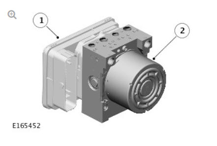
- Anti-lock Brake System (ABS) control module
- Hydraulic Control Unit (HCU)
The Anti-lock Brake System (ABS) control module controls the brake functions by operating the Hydraulic Control Unit (HCU) to modulate hydraulic pressure to the individual wheel brakes.
The ABS control module is attached to the HCU and forms an integral component. A multi-pin connector provides the electrical interface between the ABS control module and the vehicle wiring. The ABS control module may be interrogated using Land Rover approved diagnostic equipment.
HYDRAULIC CONTROL UNIT (HCU)
The Hydraulic Control Unit (HCU) is a four channel unit that modulates the supply of hydraulic pressure to the brakes, under the control of the Anti-lock Brake System (ABS) control module.
The master cylinder primary and secondary circuit outlets are connected to the HCU primary and secondary circuits.
Each of the HCU circuits contains the following components to control the supply of hydraulic pressure to the brakes:
- A normally open, solenoid-operated pilot valve, to enable active braking.
- A normally closed, solenoid-operated priming valve, to connect the brake fluid reservoir to the dual circuit hydraulic pump during active braking.
- A hydraulic pump, to generate hydraulic pressure for active braking and return brake fluid to the reservoir.
- Normally open, solenoid-operated inlet valves and normally closed, solenoid-operated outlet valves, to modulate the hydraulic pressure in the individual brakes.
- An accumulator and a relief valve, to allow the fast release of pressure from the brakes.
- Filters, to protect the internal components from contamination.
A pressure sensor in the primary circuit provides the ABS control module with hydraulic pressure signals.
Contact pins on the HCU mate with contacts on the ABS control module to provide the electrical connections from the ABS control module to the dual circuit hydraulic pump motor and the pressure sensors. The solenoids that operate the valves are installed within the ABS control module.
Hydraulic Control Unit (HCU) Schematic Diagram
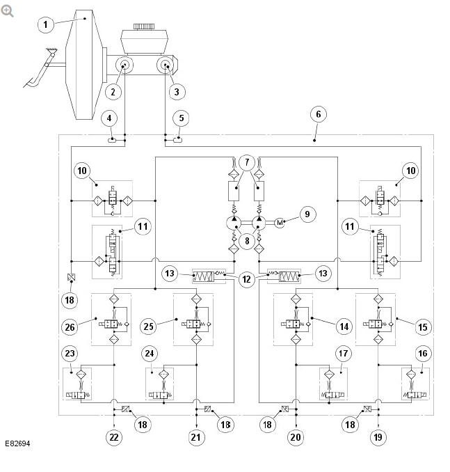
- Brake booster
- Primary hydraulic circuit
- Secondary hydraulic circuit
- Pulsation damper
- Pulsation damper
- Hydraulic Control Unit (HCU)
- Damping chamber
- Dual circuit hydraulic pump
- Direct Current (DC) motor
- Solenoid-operated pilot valve (2 off)
- Solenoid-operated priming valve (2 off)
- Check valve
- Low-pressure accumulator (2 off)
- Solenoid-operated inlet valve (Rear right brake)
- Solenoid-operated inlet valve (Front left brake)
- Solenoid-operated outlet valve (Front left brake)
- Solenoid-operated outlet valve (Rear right brake)
- Pressure sensor (5 off)
- Front left brake (secondary circuit)
- Rear right brake (secondary circuit)
- Rear left brake (primary circuit)
- Front right brake (primary circuit)
- Solenoid-operated outlet valve (Front right brake)
- Solenoid-operated outlet valve (Rear left brake)
- Solenoid-operated inlet valve (Rear left brake)
- Solenoid-operated inlet valve (Front right brake)
The Hydraulic Control Unit (HCU) features 3 operating modes:
- Normal braking/Electronic Brake Force Distribution (EBD).
- Anti-lock Brake System (ABS) braking.
- Active braking.
Normal Braking/Electronic Brake Force Distribution (EBD) Mode
Initially, all of the solenoid-operated valves are de-energized. Operating the brake pedal produces a corresponding increase or decrease of pressure in the brakes, through the open pilot valves and inlet valves. If the Anti-lock Brake System (ABS) control module determines that EBD is necessary, it energizes the inlet valves for both the rear brakes, to isolate the brakes from any further increase in hydraulic pressure. Only the rear brakes are controlled by the EBD function.
Anti-lock Brake System (ABS) Braking Mode
If the ABS control module determines that ABS braking is necessary, it energizes the inlet and outlet valves of the related brake and starts the hydraulic return pump. The inlet valve closes to isolate the brake from pressurized fluid; the outlet valve opens to release pressure from the brake into the accumulator and the return pump circuit. The reduced hydraulic pressure allows the wheel to accelerate. The ABS control module then operates the inlet and outlet valves to modulate the pressure in the brake to apply the maximum braking effort without locking the wheel. Control of the valves for each wheel takes place individually.
Active Braking Mode
The active braking mode is used to generate and control hydraulic pressure to the brakes for functions other than the normal/Electronic Brake Force Distribution (EBD) and ABS braking modes.
For active braking, the ABS control module energizes the pilot valves and priming valves, starts the return pump and energizes all of the inlet valves.
Brake fluid, drawn from the reservoir through the master cylinder and priming valve, is pressurized by the hydraulic pump and supplied to the inlet valves. The ABS control module then operates the inlet valves and outlet valves, as required, to modulate the pressure in the individual brakes. Some noise may be generated during active braking.
Service Information
The Anti-lock Brake System (ABS) control module and Hydraulic Control Unit (HCU) form a single component and must not be separated. The ABS control module and HCU assembly is supplied in a pre-filled state. After installation, the hydraulic brake system only requires a conventional bleed of the system; there is no requirement to pressure bleed the system.
READ NEXT:
 Anti-lock Control - Operation
ANTI-LOCK BRAKE SYSTEM (ABS)
The Anti-lock Brake System (ABS) controls the speed of all road wheels to
ensure optimum wheel slip when braking at the adhesion limit. The wheels
are prevented from locki
Anti-lock Control - Traction Control / Diagnosis and Testing
PRINCIPLES OF OPERATION
For a detailed description of the Anti-lock Brake System, refer to the
relevant Description and Operation section in the workshop manual. REFER
to: Anti-Lock Control - Traction
Front Disc Brake Brake Caliper Anchor Plate (G1785106) / Removal and
Installation
PART(S)
REMOVAL
NOTE:
Removal steps in this procedure may contain installation details.
WARNING:
Make sure to support the vehicle with axle stands.
Raise and support the vehicle
Refer to: Wheel and T
SEE MORE:
Selective Catalyst Reduction
(SCR) Components - EU6 only
Diesel Exhaust Fluid (DEF) tank module
Diesel Exhaust Fluid (DEF) level sensor
Diesel Exhaust Fluid (DEF) tank module electrical connection
Diesel Exhaust Fluid (DEF) pressure line connection
Diesel Exhaust Fluid (DEF) injection pump electrical connection
Diesel Exhaust Fluid (DEF) heater el
Power Transfer Unit (PTU) / Operation
POWER TRANSFER UNIT (PTU)
The Active Driveline Power Transfer Unit (PTU) input shaft is driven directly
from the transmission differential. When the hydraulically operated triple
cone synchroniser is in the disengaged position (B in the following
illustration), the crown wheel shaft and the crown wh
