Land Rover Discovery: Anti-lock Control - Traction Control / Description and Operation
COMPONENT LOCATION - SHEET1 OF 2
NOTE:
Right Hand Drive (RHD) illustration shown, Left Hand Drive (LHD) illustration similar
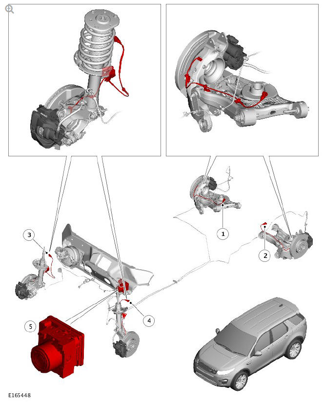
- Rear right wheel speed sensor
- Rear left wheel speed sensor
- Front right wheel speed sensor
- Front left wheel speed sensor
- Integrated Anti-lock Brake System (ABS) control module and Hydraulic Control Unit (HCU)
COMPONENT LOCATION - SHEET 2 OF 2
NOTE:
Right Hand Drive (RHD) illustration shown, Left Hand Drive (LHD) illustration similar
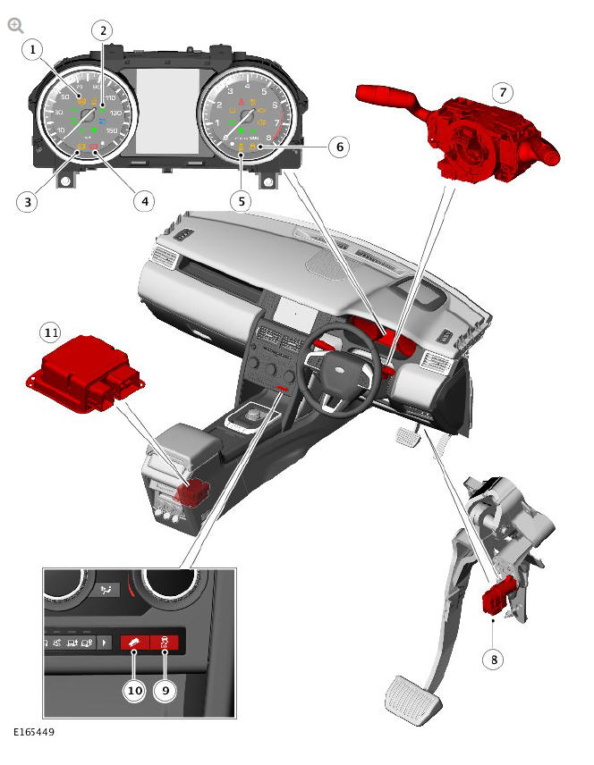
- Anti-lock Brake System (ABS) warning indicator
- Hill Descent Control (HDC) active indicator
- Brake amber warning indicator
- Brake red warning indicator
- Dynamic Stability Control (DSC) 'OFF' warning indicator
- DSC warning indicator
- Clockspring (CLKSPG)
- Brake pedal switch
- DSC switch
- HDC switch
- Restraints Control Module (RCM) - contains the yaw rate lateral acceleration sensor
OVERVIEW
The anti-lock control - traction control system features an Anti-lock Brake System (ABS) control module attached to a 4-channel Hydraulic Control Unit (HCU). The integrated ABS control module and HCU is located in the rear left side of the engine compartment, and is installed in the brake hydraulic circuit between the brake master cylinder and the four brake calipers.
The ABS control module is connected to the High Speed (HS) Controller Area Network (CAN) chassis bus, HS CAN powertrain bus, and actively interacts with other vehicle system control modules and associated sensors to receive and transmit current vehicle operating information.
When required, the ABS control module will actively intervene and operate the HCU during braking or vehicle maneuvers to correct the vehicle attitude, stability, traction or speed. During severe incidents of vehicle correction, the ABS control module will also request the Engine Control Module (ECM) to reduce engine power in order to further stabilize and correct the vehicle.
To provide full system functionality, the anti-lock control and traction control system includes the following components:
- Dynamic Stability Control (DSC) switch.
- Hill Descent Control (HDC) switch.
- HDC / All Terrain Progress Control (ATPC) switch.
- Four wheel speed sensors.
- Yaw rate lateral acceleration sensor.
- Steering angle sensor.
- Instrument Cluster (IC) warning indicators.
- Integrated ABS control module and HCU.
The anti-lock control and traction control system also provides the following brake functions that are designed to assist the vehicle or aid the driver:
- Anti-lock Brake System (ABS).
- Corner Brake Control (CBC).
- Dynamic Stability Control (DSC).
- Electronic Brake Force Distribution (EBD).
- Electronic Traction Control (ETC).
- Emergency Brake Assist (EBA).
- Engine Drag-torque Control (EDC).
- HDC, with gradient release control.
- ATPC, with gradient release control.
- Hill Start Assist (HSA).
- Yaw Stability Control (YSC).
- Terrain Response.
- Trailer brake control module.
- Intelligent Emergency Braking (IEB).
- Dynamic Stability Control (DSC) Switch
- Wheel Speed Sensors
- Steering Angle Sensor
- Anti-lock Brake System (ABC) Control Module
- Anti-lock Control - Operation
READ NEXT:
 Dynamic Stability Control (DSC) Switch
DESCRIPTION
The Dynamic Stability Control (DSC) switch is a non-latching switch installed
in the floor console, forward of the selector lever (for manual transmission
vehicles) or Transmission Contr
Wheel Speed Sensors
Retaining screw
Wheel speed sensor
Bearing seal and magnetic encoder ring
Wheel bearing
Wheel hub
An active wheel speed sensor is installed in each wheel knuckle, and
provides the Anti-lock B
Steering Angle Sensor
The steering angle sensor is integrated into the clockspring.
The clockspring is mounted to the upper steering column with two screws,
and receives an electrical supply from the main harness via a
SEE MORE:
Engine - Ingenium i4 2.0l Diesel Upper Timing Chain (G1875889) / Removal
SPECIAL TOOL(S)
PART(S)
REMOVAL
NOTE:
Removal steps in this procedure may contain installation details.
Disconnect the battery ground cable.
Refer to: Specifications (414-01 Battery, Mounting and Cables,
Specifications).
WARNING:
Make sure to support the vehicle with axle stands.
Raise and
Cameras
SURROUND CAMERA SYSTEM
It remains the driver's
responsibility to detect obstacles
and estimate the vehicle's
distance from them when
manoeuvring the vehicle.
To switch on the Surround
camera system, press the button
on the Touch screen surround.
Alternatively, select EXTRA
FEATURES on the HOME
me
