Land Rover Discovery: Active Driveline System
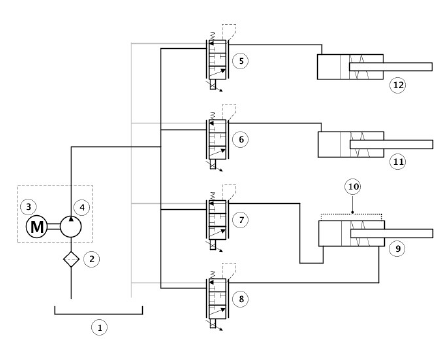
Active Driveline Hydraulic Circuit Diagram

- Reservoir
- Suction filter
- Electric actuator
- RDU pump
- Pressure Control Valve (PCV) P1
- PCV P2
- PCV P3
- PCV P4
- PTU synchroniser piston
- Bleed orifice
- Left RDU clutch piston
- Right RDU clutch piston
The Active Driveline system is controlled by the AWDCM. Using inputs from other vehicle systems, the AWDCM can automatically disconnect and connect and provide AWD to assist vehicle traction and dynamics. In normal driving conditions, the AWDCM will disconnect the Active Driveline to provide FWD to improve economy and emissions.
The AWDCM is connected to the following vehicle system control modules and MultiCAN buses:
- Anti-lock Brake System (ABS) control module - High Speed CAN Powertrain Systems bus
- Wheel speeds, ABS status, Dynamic Stability Control (DSC) status, Hill Descent Control (HDC) status and vehicle speed inputs
- Restraints Control Module (RCM) - High Speed CAN Chassis Systems bus
- Lateral acceleration inputs
- Steering Angle Sensor Module (SASM) - High Speed CAN Powertrain Systems bus
- Steering angle input
- Electric Park Brake Control Module (EPBCM) - High Speed CAN Powertrain Systems bus
- Electric park brake applied or released input
- Central Junction Box (CJB) - High Speed CAN Powertrain Systems bus
- Outputs for Touch Screen (TS) images and Instrument Cluster (IC) displays
- Terrain Response (TR) Switchpack - High Speed CAN Powertrain Systems bus
- Selected TR mode selection input
- Engine Control Module (ECM) - High Speed CAN Powertrain Systems bus
- Engine torque, accelerator pedal position, ambient temperature, RDU Clutch temperature calculation
- Transmission Control Switch (TCS) - High Speed CAN Powertrain Systems bus
- Gear position
- Transmission Control Module (TCM) - High Speed CAN Powertrain Systems bus.
- Transmission status (automatic transmission only)
The AWDCM is connected by hardwired connection to the RDU pump and the AWD valve block. The AWDCM provides a PWM output to the motor and receives three inputs from the motor position sensors.
Low side driver outputs from the AWDCM control the pressure control valve solenoids for control and operation of each of the pressure control valves.
The AWDCM will automatically connect the PTU synchroniser and operate the RDU clutches at speeds below 20 km/h (12 mph) to provide improved traction when the vehicle is pulling away from a standstill in a straight line.
The system disconnects the driveline at speeds above 35 km/h (22 mph) to improve efficiency.
NOTE:
AWD is always provided when reverse gear is selected.
The AWDCM evaluates the received inputs and can predict when AWD will be required. Typical inputs for the evaluation are received from the Accelerator Pedal Position (APP) sensor, engine torque request from TCM (transmission control module), steering angle from the Steering Angle Sensor Module (SASM) and lateral acceleration from the RCM (restraints control module).
Loss of traction is detected from inputs from the ABS (anti-lock brake system) control module. Wheel spin, ABS and Dynamic Stability Control (DSC) activity and yaw signals. Evaluation of these inputs will cause the AWDCM to connect the Active Driveline.
The AWDCM will automatically connect the PTU synchroniser and operate the RDU clutches to provide improved traction when the vehicle is pulling away from a standstill in a straight line, driving forward at speeds below 35 km/h (22 mph) and when in reverse gear.
The AWDCM will also operate the Active Driveline in AWD when the driver has selected a Terrain Response Auto2 mode that requires AWD. AWD is also activated when Hill Descent Control (HDC) is requested.
When ambient temperatures are below -10ºC (-50ºF), the AWDCM will keep the Active Driveline connected. When the vehicle is stationary and the engine is stopped, the Active Driveline will remain connected.
The RDU clutches can be fully or partially applied on each driveshaft individually to provide active torque biasing. The AWDCM can determine the clutch torque required for each halfshaft based on inputs for acceleration, yaw and oversteer or understeer. This allows the RDU to be locked to perform in a similar manner to a Limited Slip Differential.
Active Torque Biasing
.jpg)
- Accelerator pedal depressed - torque bias to outer wheel to reduce under steer
- Accelerator pedal released - increased locking torque applied to both wheels to reduce over steer
Torque biasing uses the RDU and the vehicle brakes to constantly balance the distribution of engine torque between the four wheels during cornering, resulting in improved grip and steering, and a reduced level of understeer.
The system also uses the ABS control module, monitoring the vehicle 100 times per second. As the car accelerates through a corner, the system uses yaw sensors to detect understeer, increasing engine torque along with subtle levels of braking to correct the vehicle attitude. Transferring engine torque to the outside wheels which have more grip maintains traction and steering control.
The torque biasing is also active in off-road conditions, with different settings according to the Terrain Response mode. It can be very effective in conditions such as sand, where it helps the vehicle turn in and avoid excessive understeer.
CONTROL DIAGRAM
NOTE:
A = Hardwired; AM = High Speed CAN Chassis Systems Bus; AN = High Speed CAN Powertrain Systems Bus
.jpg)
- All Wheel Drive Control Module (AWDCM)
- Terrain Response (TR) switchpack
- Gateway Module (GWM)
- Engine Control Module (ECM)
- Steering Angle Sensor Module (SASM)
- Anti-lock Brake System (ABS) control module
- Transmission Control Module (TCM)
- Rear Drive Unit (RDU) pump actuator
- All Wheel Drive (AWD) valve block
- Ground
- Fused permanent 12V power supply from Central Junction Box (CJB)
- Ignition relay
- 12V power supply from Battery Junction Box (BJB)

