Land Rover Discovery: Engine System - General Information Cylinder Compression Test - Ingenium i4 2.0l Diesel (G1817137) / General Procedures
GENERAL EQUIPMENT
Compression tester (petrol/diesel)
Land Rover diagnostic equipment
CHECK
CAUTIONS:
- Before disconnecting any components, make sure the area is clean and free from foreign material. When disconnected all openings must be sealed.
- The vehicle battery must be in good condition and fully charged before carrying out this procedure.
NOTES:
- This procedure contains some variation in the illustrations depending on the vehicle specification, but the essential information is always correct.
- This procedure contains illustrations showing certain components removed to provide extra clarity.

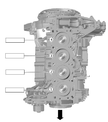
Print graphic number E176229 for use later in this procedure.
Remove the glow plugs.
Refer to: Glow Plugs (303-07B Glow Plug System - INGENIUM I4 2.0L Diesel, Removal and Installation).
CAUTION:
Make sure the fuel injection system is disabled before carrying out a cylinder compression test. Failure to follow this step may result in damage to the vehicle.
.jpg)
Disconnect the fuel injector electrical connectors.
Crank engine for approximately 5 seconds to remove any remaining fuel in the cylinders.
.jpg)
Install the compression test gauge.
Torque: 10 Nm
NOTE:
This step requires the aid of another technician.
.jpg)
- Crank the engine for 10 seconds, use illustration E176229 to record the figure displayed on the compression test gauge.
- Make sure the pressure is released from the compression test gauge after each cylinder recording.
- Remove the compression test gauge. Repeat the procedure for the remaining cylinders.
The minimum cylinder compression reading recorded must be within 10% of the maximum cylinder compression reading recorded. If the difference across the cylinders is higher than 10% please contact dealer technical support (DTS) for further assistance
Connect the fuel injector electrical connectors.
Install the glow plugs.
Refer to: Glow Plugs (303-07B Glow Plug System - INGENIUM I4 2.0L Diesel, Removal and Installation).
Using Landrover approved diagnostic equipment, read and clear any diagnostic trouble codes (DTCs).
Engine System - General Information Cylinder Head Distortion (G1802943) General Procedures
CHECK
.jpg)
Using a suitable metallic straight edge and feeler gauge, measure the cylinder head face in the areas illustrated. Note the maximum value.
CAUTION:
Machine the minimum thickness of material from the cylinder head to meet specification. If a selection of cylinder head gaskets are available, increase the thickness of the cylinder head gasket by one size.
NOTES:
- Prior to having the cylinder head machined, prior approval is required by Jaguar or Land Rover engineering.
- If the cylinder head requires machining, this must be carried out by a local engineering company.
If the cylinder head exceeds the maximum value (0.2mm), the cylinder head must be machined.
Engine System - General Information Exhaust Manifold Cleaning and Inspection (G61240) General Procedures
GENERAL PROCEDURES
- Inspect the cylinder head joining flanges of the exhaust manifold for evidence of exhaust gas leaks.
- Inspect the exhaust manifold for cracks, damaged gasket surfaces, or other damage that would make it unfit for further use.

