Land Rover Discovery: Fuel Filter Assembly - Water in Fuel (WIF) Sensor

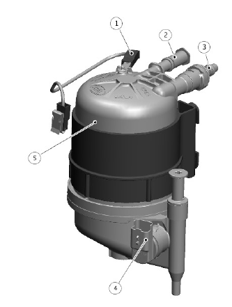
- Fuel filter ground connection
- Fuel filter inlet
- Fuel filter outlet
- Water In Fuel (WIF) sensor
- Fuel filter housing
The water in fuel sensor is located in the base of the fuel filter and is hardwired to the ECM. The sensor operates on the principle of differing resistance values to the transmission of current through water and fuel.
When the volume of water in the fuel reaches 85 cm³ or more, the sensor value is sensed by the ECM. The ECM transmits a message on the HS-CAN powertrain systems bus to the IC which displays a message 'WATER IN FUEL VISIT DEALER' in the message center.
FUEL PUMP DRIVER MODULE (FPDM)

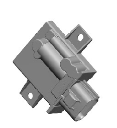
Operation of the fuel pump in the fuel tank mounted fuel pump module is regulated by the Fuel Pump Driver Module (FPDM) which is controlled by the ECM. The FPDM regulates the flow and pressure supplied by controlling the operation of the fuel pump using a PWM output.
The PWM signal from the ECM tells the FPDM the required speed for the fuel pump. The on time of the PWM signal represents half the fuel pump speed; for example, if the PWM signal has an on time of 50 %, the FPDM drives the pump at 100 %.
The FPDM will only energize the fuel pump if it receives a valid PWM signal, with an on time of between 4 % and 50 %. To switch the fuel pump off, the ECM transmits a PWM signal with an on time of 75%.
The ECM receives a monitoring signal from the FPDM. Any Diagnostic Trouble Codes (DTC) produced by the FPDM are stored by the ECM. DTC' can be retrieved from the ECM using an approved diagnostic system. The FPDM itself cannot be interrogated by the approved diagnostic system.
VARIABLE COOLANT PUMP

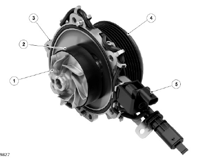
- Impeller
- Shroud
- Coolant pump housing
- Pulley
- Solenoid
The variable coolant pump is located on the upper left side of the engine within a cavity in the cylinder block.
The ECM receives input signals from other engine control components to determine the required level of cooling such as cylinder head temperature, EGR temperatures, ambient temperatures, drive mode, coolant temperature and minimum flow map. The calibration is able to control the variable coolant pump flow in five steps and is controlled by an open-loop map.
The control of the shroud solenoid is by a PWM signal from the ECM. The internal pressure within the pump acts against a return spring in the housing. Without a signal from the ECM the solenoid is de-energized, the shroud is at its default position held under return spring force, resulting in full flow from the pump.
During an engine cold start, the impeller is fully covered by the shroud (flow mode 0), therefore no coolant is circulated through the cylinder block. As the engine coolant temperature increases, the flow requirement will increase in 4 stages (flow mode 1-4). The variable coolant pump is controlled by the ECM to provide the minimum flow to support all cooling requests from the engine systems. When the engine coolant temperature reaches 85 ºC (185 ºF), the solenoid is de-energized and the shroud will move to its default fully open position (flow mode 4) allowing maximum circulation through the cylinder block. Temperature control and flow is then managed by the ECM and the electric thermostat.

