Land Rover Discovery: Manual seats / Electric seats
Manual seats

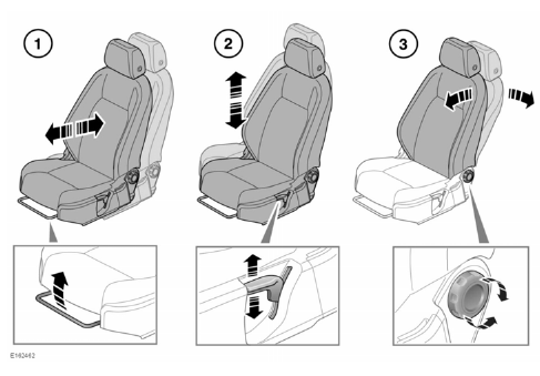
- Forward and rearward adjustment.
- Height adjustment.
- Seatback angle adjustment.
For information on how to adjust the front head restraint
Do not adjust the seat while the vehicle is moving; doing so could cause a loss of vehicle control and personal injury.
Electric seats

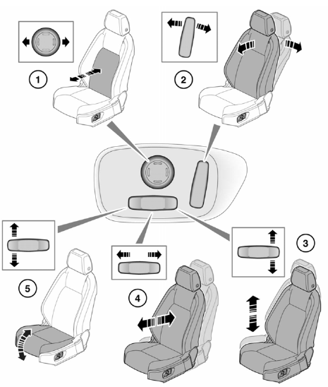
- Lumbar support adjustment.
- Seatback angle adjustment.
- Height adjustment.
- Forward and rearward adjustment.
- Cushion angle adjustment.
To adjust the seats, the Smart key must be inside the vehicle.
For information on how to adjust the front head restraints
Do not adjust the seat while the vehicle is moving; doing so could cause a loss of vehicle control and personal injury.
Restricted front seat travel
If seat movement stops unexpectedly during adjustment, check for and remove any obstructions.
Once any obstructions have been removed, the seat adjustment mechanism can be reset as follows: Operate the button again to continue the stalled adjustment. When seat movement resumes, hold the button until the end of travel in that direction has been reached.
Seat adjustment can now be carried out as normal.
Note: If no obstructions can be seen, but normal adjustment cannot be carried out without stalling, contact your Retailer/ Authorised Repairer.

