Land Rover Discovery: Rear Drive Axle- Differential - Vehicles without- Active Driveline/ Diagnosis and Testing
PRINCIPLES OF OPERATION
For a detailed description of the Rear Differential, refer to the relevant Description and Operation section in the workshop manual. REFER to: Rear Drive Axle and Differential (205-02A Rear Drive Axle/Differential - Vehicles Without: Active Driveline, Description and Operation).
INSPECTION AND VERIFICATION
CAUTION:
Diagnosis by substitution from a donor vehicle is NOT acceptable.
Substitution of control modules does not guarantee confirmation of a fault, and may also cause additional faults in the vehicle being tested and/or the donor vehicle.
NOTES:
- If a control module or a component is suspect and the vehicle remains under manufacturer warranty, refer to the Warranty Policy and Procedures manual, or determine if any prior approval programme is in operation, prior to the installation of a new module/component.
- When performing voltage or resistance tests, always use a digital
multimeter that has the resolution ability to view 3 decimal places.
For example, on the 2 volts range can measure 1mV or 2 K Ohm range can measure 1 Ohm. When testing resistance always take the resistance of the digital multimeter leads into account.
- Check and rectify basic faults before beginning diagnostic routines involving pinpoint tests.
- Verify the customer concern
- Visually inspect for obvious signs of damage and system integrity
Visual inspection
.jpg)
- If an obvious cause for an observed or reported concern is found, correct the cause (if possible) before proceeding to the next step
- If the cause is not visually evident, verify the symptom and refer to the Symptom Chart, alternatively check for Diagnostic Trouble Codes (DTCs) and refer to the DTC Index
- Check DDW for open campaigns. Refer to the corresponding bulletins and SSMs which may be valid for the specific customer complaint and carry out the recommendations as required
IDENTIFY THE CONDITION
Gear Howl and Whine
Howling or whining of the ring gear and pinion is due to an incorrect gear pattern, gear damage or incorrect bearing preload.
Bearing Whine
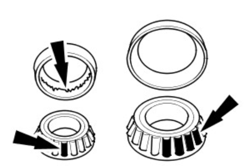
Bearing whine is a high-pitched sound similar to a whistle. It is usually caused by worn/damaged pinion bearings, which are operating at driveshaft speed. Bearing noise occurs at all driving speeds. This distinguishes it from gear whine which is speed dependent.

As noted, pinion bearings make a high-pitched, whistling noise, usually at all speeds. If however there is only one pinion bearing that is worn/damaged, the noise may vary in different driving phases.
A wheel bearing noise can be mistaken for a pinion bearing noise.
Chuckle
Chuckle that occurs on the coast driving phase is usually caused by excessive clearance between the differential gear hub and the differential case bore.
Damage to a gear tooth on the coast side can cause a noise identical to a chuckle. A very small tooth nick or ridge on the edge of a tooth can cause the noise.
.jpg)
Knock
Knock, which can occur on all driving phases, has several causes including damaged teeth or gearset.
.jpg)
A gear tooth damaged on the drive side is a common cause of the knock.
.jpg)
Clunk
Clunk is a metallic noise heard when the automatic transmission is engaged in REVERSE or DRIVE. The noise may also occur when the throttle is applied or released. Clunk is caused by transmission calibration, backlash in the driveline or loose suspension components and is felt or heard in the vicinity of the rear drive axle.
Bearing Rumble
Bearing rumble sounds like marbles being tumbled. This condition is usually caused by a worn/damaged wheel bearing. The lower pitch is because the wheel bearing turns at only about one-third of the driveshaft speed. Wheel bearing noise also may be high-pitched, similar to gear noise, but will be evident in all four driving modes.
SYMPTOM CHART
.jpg)
.jpg)
.jpg)
PINPOINT TESTS
.jpg)
DTC INDEX
For a list of Diagnostic Trouble Codes (DTCs) that could be logged on this vehicle, please refer to Section 100-00. REFER to: Diagnostic Trouble Code Index - DTC: All Wheel Drive Control Module (AWDCM) (100-00 General Information, Description and Operation).
Rear drive axle_differential - vehicles without- active driveline specifications
Lubrication
.jpg)
General Specification
.jpg)
Torque Specifications
.jpg)
.jpg)
* New nuts/bolts must be installed

