Land Rover Discovery: Steering Column / Description and Operation
COMPONENT LOCATION

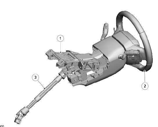
- Upper column
- Steering wheel
- Intermediate shaft
OVERVIEW
The steering column consists of an intermediate shaft, the upper column and the steering wheel, which are connected together to transfer driver steering inputs to the steering gear.
The steering column incorporates rake and reach adjustment, an Electric Steering Column Lock (ESCL) or dummy lock (dependent on market) and a steering column collapse actuator (North American Specification (NAS) only). Some vehicles also incorporate a steering wheel heater. Multifunction switches are attached to the steering wheel module on the upper column and to the steering wheel, for operation of the following vehicle systems:
- Exterior lighting.
For additional information, refer to: Exterior Lighting (417-01 Exterior Lighting, Description and Operation).
- Wipers and washers.
For additional information, refer to: Wipers and Washers (501-16 Wipers and Washers, Description and Operation).
- Speed control.
For additional information, refer to: Speed Control (310-03 Speed Control, Description and Operation).
- Steering wheel heater. For additional information see this section.
- Audio/Video.
For additional information, refer to: Audio System (415-01 Information and Entertainment System, Description and Operation).
- Vehicle information and settings menu.
For additional information, refer to: Information and Message Center (413-08 Information and Message Center, Description and Operation).
- Telephone and voice control.
For additional information, refer to: Cellular Phone (415-01 Information and Entertainment System, Description and Operation).
The steering wheel also incorporates the driver air bag, with integrated horn switch.
For additional information, refer to: Airbag Supplemental Restraint System (501-20B Supplemental Restraint System, Description and Operation).
On automatic transmission vehicles, two paddle switches are attached to the steering wheel.
For additional information, refer to: External Controls (307-05 Automatic Transmission/Transaxle External Controls, Description and Operation).
DESCRIPTION
INTERMEDIATE SHAFT
.jpg)
- Outer tube
- Upper universal joint
- Inner tube
- Lower universal joint
The intermediate shaft consists of inner and outer steel tubes that can move telescopically to:
- Permit system assembly.
- Allow steering wheel adjustment.
- Isolate the steering wheel from any movement of the steering gear in the event of a vehicle impact.
An isolator, on the inner tube, reduces Noise, Vibration and Harshness (NVH) in the steering column. Universal joints connect the ends of the intermediate shaft to the upper column and the input shaft of the steering gear.
UPPER COLUMN
.jpg)
- Steering column collapse actuator (NAS only)
- Upper shroud
- Screw (2 off)
- Switchgear assembly
- Lower shroud
- Screw (2 off)
- Immobilizer Antenna Unit (IAU) transceiver (where fitted)
- Rake adjustment slot
- Upper column shaft
- Bearing housing
- Adjustment locking lever
- Reach adjustment slot
- Locking mechanism
- Electric Steering Column Lock (ESCL)
- Pivot pin
- Reach adjustment slots
- Outer bracket
- Energy management plate
- Inner bracket
The shaft of the upper column is installed in a bearing housing that is attached to an inner bracket with a pivot pin and an adjustment locking mechanism. Slots at the attachment points, in the bearing housing and the inner bracket, allow the bearing housing to move axially and to tilt in the inner bracket, to provide the rake and reach adjustment of the steering wheel. The locking mechanism is a friction lock, operated by a lever turning a cam disc.
The inner bracket is located on rails in an outer bracket, which is attached to the cross car beam. The inner and outer brackets are locked together by an energy management plate, which is attached to both brackets with screws.
In a serious impact, to prevent excessive force causing injury as the driver strikes the air bag, the inner bracket progressively moves forwards on the rails in the outer bracket. The movement is controlled by the energy management plate. The plate has leaves attached to the inner bracket, which peel back in a controlled manner, absorbing energy and allowing the steering wheel to move with the driver.
The steering wheel module is attached to the top of the upper column by two bolts. The module incorporates the clockspring and the multifunction switches for the exterior lighting and the windows and washers.
Upper and lower shrouds cover that part of the upper column not concealed by the instrument panel. On vehicles with passive entry passive start, an Immobilizer Antenna Unit (IAU) transceiver is installed in the lower shroud.
For additional information, refer to: Anti-Theft - Passive (419-01B Anti-Theft - Passive, Description and Operation).
ELECTRIC STEERING COLUMN LOCK (WHERE FITTED)
An Electric Steering Column Lock (ESCL) is attached to the underside of the bearing housing.
In markets where an electric steering column lock is not fitted, a dummy lock is installed to provide a forward attachment point for the steering column lower cowl, and the electric steering column lock is disabled in the car configuration files.
For additional information, refer to: Anti-Theft - Passive (419-01B Anti-Theft - Passive, Description and Operation).
STEERING COLUMN COLLAPSE ACTUATOR (NAS ONLY)

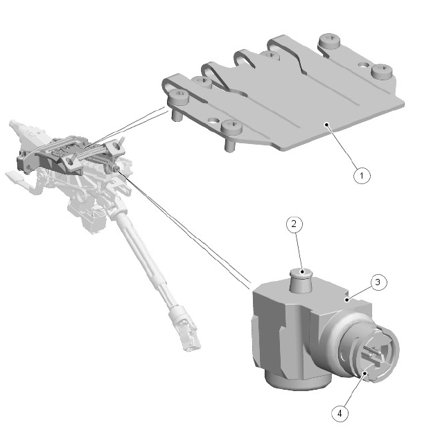
- Energy management plate
- Pin
- Steering column collapse actuator
- Electrical connector
A steering column collapse actuator is installed to provide increased energy absorption, if a crash situation occurs.
The steering column collapse actuator is located below the energy management plate. A pin on the actuator is engaged in a hole in the central leaf of the energy management plate.
When the system detects that the driver seat belt is buckled, and a crash situation occurs which activates the airbags, the device fires, which retracts the pin. This reduces the energy absorption to a level suitable for a restrained (belted) driver.
STEERING WHEEL
.jpg)
- Downshift paddle switch (automatic transmission only)
- Upshift paddle switch (automatic transmission only)
- Left multifunction switchpack
- Right multifunction switchpack
- Heater mat connector
- Heated steering wheel module
- Steering wheel securing screw
- Driver air bag
The steering wheel is located on the hexagonal drive end of the upper column shaft and secured with a screw.
The driver air bag and two multifunction switchpacks are installed in the center of the steering wheel. On automatic transmission vehicles, upshift and downshift paddle switches are attached to the front of the steering wheel. A link harness connects the steering wheel components to the clockspring.
STEERING WHEEL HEATER (WHERE FITTED)
The steering wheel heater consists of a heater mat and a Negative Temperature Coefficient (NTC) temperature sensor installed around the rim of the steering wheel under the trim. A steering wheel heater control module, integrated into the link harness, regulates the temperature of the heater mat. A switch on the left multifunction switchpack switches the heater on and off.
A heater symbol in the switch is illuminated amber when the steering wheel heater is on. When the steering wheel heater is off, the symbol is either not illuminated or, if the exterior lighting is on, illuminated green.
OPERATION
STEERING WHEEL HEATER (WHERE FITTED)
The steering wheel heater control module receives a power supply from the extended ignition relay in the Battery Junction Box (BJB) via the clockspring.
When the driver operates the steering wheel heater switch, a path is completed between the switch and the steering wheel heater control module, which then supplies power to the heater mat. The steering wheel heater control module monitors the heater mat temperature using the temperature sensor, and controls the power supply to keep the heater mat at the optimum temperature.
CONTROL DIAGRAM
A = Hardwired connection.
.jpg)
- Heated steering wheel module
- Clockspring
- Heater mat and temperature sensor
- Ground wire
- Power supply
- Heated steering wheel switch

