Land Rover Discovery: TAS Graphics
Land Rover Discovery (2009–2016) Service Manual / General Information / About This Manual / TAS Graphics
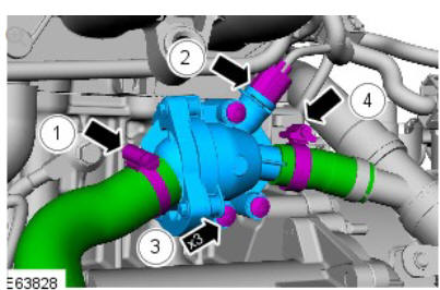
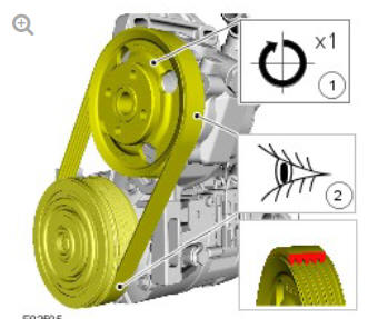
Colors used in the graphic are as follows:
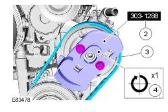
- Blue - Indicates the target item, item to be removed/installed or disassembled/assembled
- Green and Brown - Indicates a secondary item that needs to be detached, removed/installed or disassembled/assembled prior to the target item
- Yellow - Component that is touched or affected in a way but remains in the vehicle. It may be detached, attached, moved, modified, checked, adjusted etc.
- Magenta - Indicates electrical connectors and fasteners such as nuts, bolts, clamps or clips
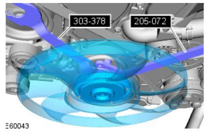
- Pale Blue - is for the special tool(s) and general equipment.
There may be multiple steps assigned to one illustration.
Numbered pointers are used to indicate the number of electrical connectors and fasteners such as nuts, bolts, clamps or clips.
Items in the illustration can be transparent or use cutouts to show hidden detail(s).
READ NEXT:
 TAS Symbols
Symbols are used inside the graphics and in the text area to enhance the
information display. The following paragraphs describe the various types
and categories of symbols.
Prohibition symbols advise
Diesel Fuel System Health and Safety Precautions
DESCRIPTION AND OPERATION
WARNINGS:
Fuel may not give adequate warning before toxic or harmful
effects
arise.
Exposure to fuel can be harmful and can cause severe health
damage or death.
Prov
General Service Information
INTRODUCTION
This manual has been written in a format that is designed to meet the needs
of Land Rover technicians worldwide and to assist them in the efficient
repair and maintenance of Land Rover ve
SEE MORE:
Engine System - General
Information Cylinder
Compression Test - Ingenium i4 2.0l Diesel (G1817137)
/ General Procedures
GENERAL EQUIPMENT
Compression tester (petrol/diesel)
Land Rover diagnostic equipment
CHECK
CAUTIONS:
Before disconnecting any components, make sure the area is clean
and free from foreign material. When disconnected all openings
must be sealed.
The vehicle battery must be in good condition and
Telematics Control Module (TCU)
Battery cover
Battery pack
Battery tray
Electrical connector
GPS antenna connector
GSM antenna connector
Telematics Control Module
The TCU is located in the right rear corner of the luggage
compartment,
behind the trim panel.
For security reasons the TCU is located in a position that is
© 2019-2026 Copyright www.lrdisc.com
