Land Rover Discovery: TAS Symbols
Symbols are used inside the graphics and in the text area to enhance the information display. The following paragraphs describe the various types and categories of symbols.
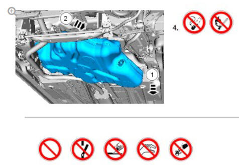
Prohibition symbols advise on prohibited actions to either avoid damage or health and safety related risks.
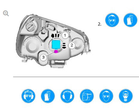
Health and Safety symbols recommend the use of particular protection equipment to avoid or at least reduce the risk or severity of possible injuries.
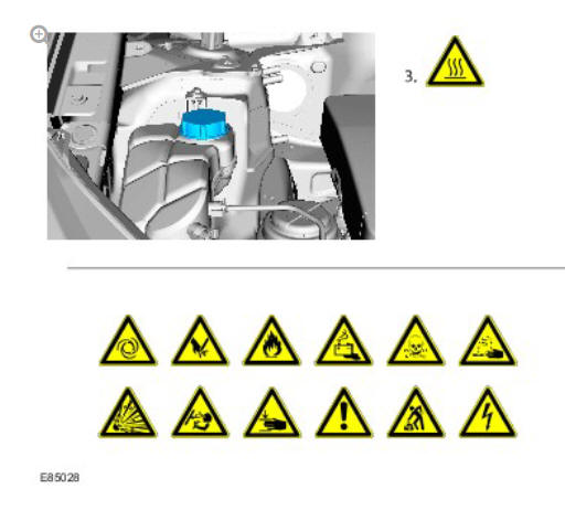
Warning symbols are used to indicate potential risks resulting from a certain component or area.
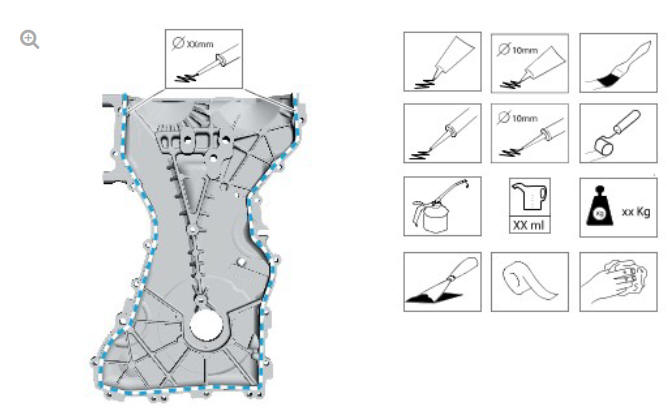
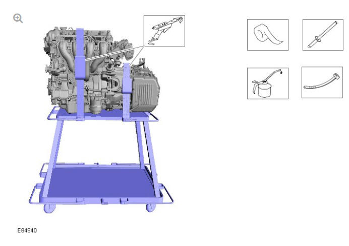
Instruction symbols are used to apply sealer, lubricant, weight, tape or cleaning detergent to a component.
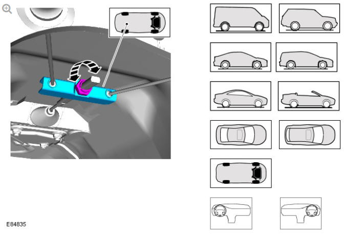
Location symbols are used to show the location of a component or system within the vehicle.
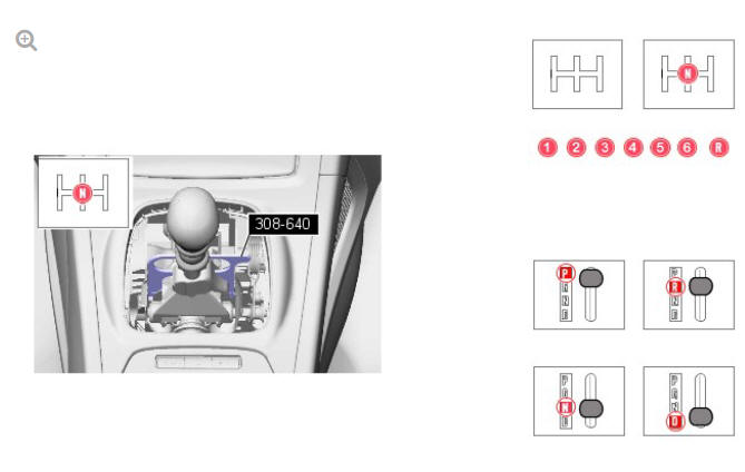
Gearshift lever or selector lever position symbols are used to show which gearshift lever or selector lever position is to be set.
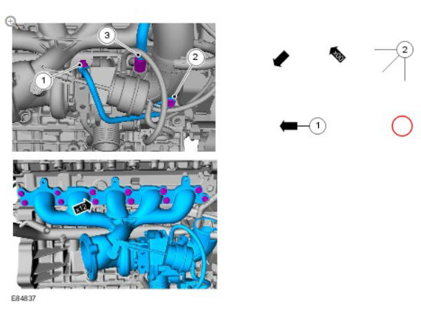
Pointer symbols are used to draw the attention to components and give special instructions such as a required sequence or number of components.
The number of components is reflected by the value inside the luty arrow. A sequence number is located inside the circle. Numbers inside circles are also used to allocate special information such as tightening torques or chemicals to a particular component.
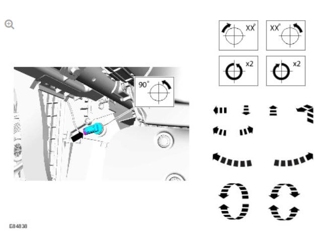
Movement arrows are used to show three dimensional or rotational movements. These movements can include specific values inside the symbol if required.
Standard tool symbols recommend the use of certain standard tools. These tools can include dimension values if required.
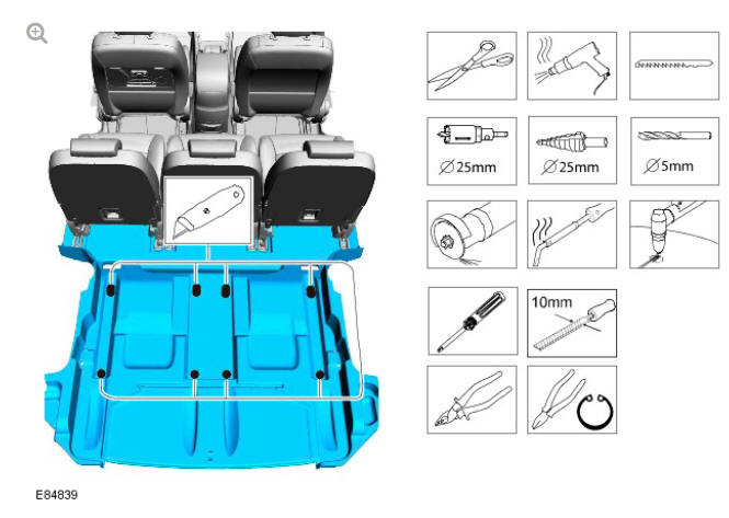
The following graphic illustrates a set of symbols that are used to provide detailed information on where to apply a material.
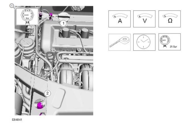
Measurement symbols provide detailed information on where to carry out a specific measurement. These symbols can include specific values if required.
Special Tools and Torque Figure(s)
Special tools will be shown with the tool number in the illustration. The special tool number(s), general equipment, material(s) and torque figure(s) used for the procedure step will be shown in the text column.
READ NEXT:
 Diesel Fuel System Health and Safety Precautions
DESCRIPTION AND OPERATION
WARNINGS:
Fuel may not give adequate warning before toxic or harmful
effects
arise.
Exposure to fuel can be harmful and can cause severe health
damage or death.
Prov
General Service Information
INTRODUCTION
This manual has been written in a format that is designed to meet the needs
of Land Rover technicians worldwide and to assist them in the efficient
repair and maintenance of Land Rover ve
Health and Safety Precautions
INTRODUCTION
Modern vehicles contain many materials and liquids which if not handled
with care can be hazardous to both personal health and the environment.
Also, many of the procedures associated wi
SEE MORE:
Exterior Lighting / Description and Operation
COMPONENT LOCATION
Graphic: 1 off 2.
Stop lamp switch
Rain/Light sensor
Side turn signal indicator lamp
Headlamp
Front fog lamp
Battery Junction Box (BJB)
Reverse lamp switch
Graphic: 2 off 2.
High Mounted Stop Lamp (HMSL)
License plate lamp
Front height sensor (Xenon headlamps only)
General Rules for Battery
Care
GENERAL RULES FOR BATTERY CARE
2.1 RETAILER SHOWROOM/DEMONSTRATION VEHICLES
Vehicles used as retailer demonstrator(s), in a showroom, must be
connected to a JLR approved showroom conditioner capable of delivering
50 Amps. This will prevent the battery from being damaged.
Vehicles used as retaile
