Land Rover Discovery: Tool kit
5 seat vehicles
Lift the loadspace floor to access the temporary use spare wheel and tool kit.
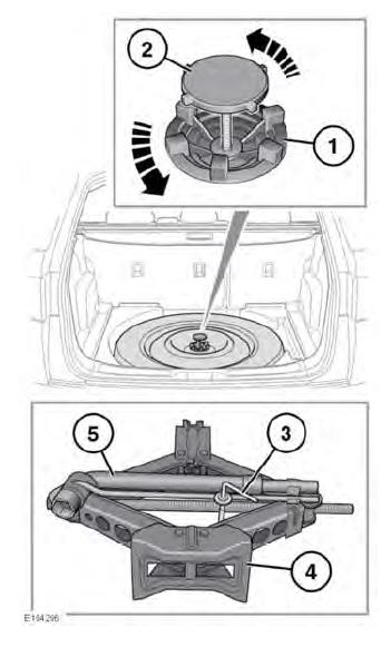
- Temporary use spare wheel locking ring.
- Temporary use spare wheel retaining bolt.
- Tool kit retaining bolt.
- Jack.
- Wheel brace.
Secure the spare wheel, or the removed wheel, in the correct position using the retaining bolt.
7 seat vehicles
Lift the loadspace floor to access the tool kit.
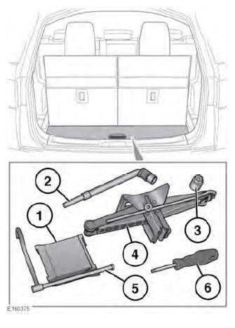
- Wheel chocks.
- Wheel brace.
- Locking wheel nut adaptor.
- Jack.
- Winch handle for lowering the temporary use spare wheel.
- Rear bumper cover removal tool.
Note: Examine the jack occasionally, clean and grease the moving parts, particularly the screw thread, to prevent corrosion.
READ NEXT:
 Removing the spare wheel
Remove the temporary spare
wheel prior to jacking the vehicle,
to avoid destabilising the vehicle
when raised.
Wheels are heavy and if handled
incorrectly may cause injury. Use
extreme caution
Using wheel chocks
Note: Not all vehicles have wheel chocks
supplied as part of the tool kit.
Wheel chocks are a useful addition to a
vehicle's tool kit. Note the following
advice when using wheel chocks:
Before raisi
Wheel changing
Before raising the vehicle, refer
to all warnings at the beginning
of this section of the Owner's
Handbook.
Before changing a wheel, read and
observe the warnings
If your vehicle is fitted with side
s
SEE MORE:
Engine - Ingenium i4 2.0l Diesel Flexplate (G1875884) / Removal and
Installation
SPECIAL TOOL(S)
PART(S)
REMOVAL
CAUTION:
Under no circumstances should the flexplate retaining bolts be
inserted into the crankshaft with the flexplate removed. Failure to
follow this instruction will result in damage to the engine.
NOTE:
Some variation in the illustrations may occur, but the
Rear Drive Axle - Differential - Vehicles with- Active Driveline Electric
Hydraulic Pump (G1781303) / Removal and Installation
REMOVAL
NOTE:
Removal steps in this procedure may contain installation details.
WARNING:
Make sure to support the vehicle with axle stands.
Raise and support the vehicle.
NOTE:
Before disconnect any components of the active driveline
hydraulic system, the two pipe port closing valve must be
closed m
© 2019-2026 Copyright www.lrdisc.com
