Land Rover Discovery: Wipers and Washers Control Switch - Description
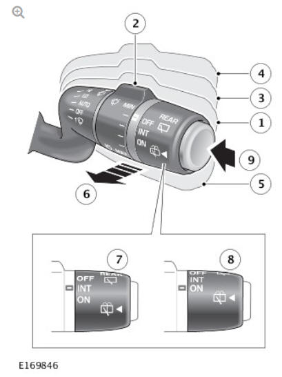
- Vehicles with rain/light sensor - Automatic rain sensing selected/intermittent wipe selected if sensor disabled in IC menu or Vehicles without rain/light sensor - Intermittent wipe selected
- Vehicles with rain/light sensor - Automatic rain sensing sensitivity adjustment/intermittent delay adjustment if sensor disabled in IC menu or Vehicles without rain/light sensor - Intermittent delay adjustment
- Low speed wipe
- High speed wipe
- Single wipe or hold for continuous wipe
- Windshield wash/wipe
- Rear window wiper - intermittent wipe
- Rear window wiper - continuous wipe
- Rear window wash/wipe
All windshield wiper and rear window wiper functions are controlled by the driver using the wipers and washers control switch. The control switch is part of the clockspring assembly located on the steering column.
The outputs from the switches are converted to Local Interconnect Network (LIN) bus outputs and are passed from the clockspring to the Central Junction Box (CJB). The CJB processes the LIN bus signals and activates the selected function via relays and outputs to the Rear Junction Box (RJB) and Battery Junction Box (BJB).
Wiper Service Position - Description
The wiper service position allows the windshield wipers to be parked in a position to allow easy access to the wiper blades for replacement.
NOTE:
The smart key must remain in the vehicle when the windshield wipers are in the service position.
Perform the following steps to set the windshield wipers service position:
- Make sure the ignition is off (power mode 0)
- Put the ignition on (power mode 6) and then to off again (power mode 0)
- Immediately move the wipers and washers control switch down to the single wipe position and put the ignition on again (power mode 6)
- The windshield wipers will move to the service position.
To return the windshield wipers to the normal park position perform the following steps:
- Put the ignition to off (power mode 0)
- The windshield wipers will return to the park position.
WINTER PARK POSITION
The winter park position allows the windshield wipers to be set at a higher than normal park position. This allows the windshield wipers to be lifted from the screen to prevent freezing to the windshield and to allow snow or an obstruction to be removed.
The winter park position is enabled or disabled using the instrument cluster menu. Press the 'Menu/OK' switch to open the menu and navigate to select 'Wiper Winter Park'. Press the 'Menu/OK' switch to select or deselect the function.
WINDSHIELD WIPER LIMP HOME MODE
If a failure of the Local Interconnect Network (LIN) bus occurs between the CJB and the wipers and washers control switch, when the windshield wipers are active, the CJB will initiate limp home mode.
The CJB will run the windshield wipers continuously at slow speed whilst an active front wiper mode is selected.
READ NEXT:
 Windshield Wiper Fast/Slow/Single Wipe - Operation
OPERATION
Slow Wipe
When the driver moves the wipers and washers control switch to the slow
wipe position, the Central Junction Box (CJB) detects a Local Interconnect
Network (LIN) bus message and ene
Rear Window Wiper - Operation
When the driver moves the wipers and washers control switch to the rear
window wiper position, the CJB detects a LIN bus message and will
energize the rear window wiper relay which is integral with th
Headlamp Washers - Operation
When the engine is running (power mode 7) and the CJB has received a
headlamps 'ON' LIN bus message from the lighting control switch, when the
driver operates the wipers and washers control switch in
SEE MORE:
Rear Drive Unit (RDU)
Drive flange
Mounting bracket
RDU pump
All Wheel Drive (AWD) valve block oil filler plug
AWD Valve block
PTU synchroniser piston pressure line P4
PTU synchroniser piston pressure line P3 including pressure damper
Left RDU clutch pressure line P2
Right RDU clutch pressure line P1
RDU oil
Clutch Pedal Position Sensor (Manual Ransmission Vehicles Only)
The clutch pedal position sensor provides the ABS control module with a
continuous measure of clutch pedal position.
The clutch pedal position sensor is attached to the clutch master cylinder.
The sensor is a permanent magnet linear contactless displacement type
sensor.
The signal from the clut
