Land Rover Discovery: Rain/Light Sensor (If Fitted) - Description
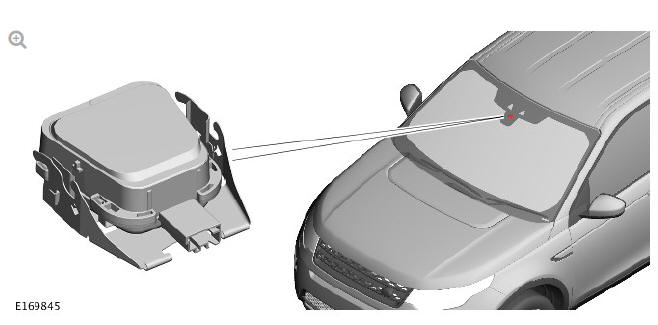
The rain/light sensor is located at the upper edge of the windshield, behind the interior rear view mirror trim panel. Contact between the rain sensor and windscreen is provided via a silicon pad which is compressed during the assembly process by two locking retaining clips either side of the sensor.
The rain/light sensor unit attaches to the windshield via a retaining clamp, which latches onto formed tags on the windshield bracket.
The rain/light sensor provides information to the CJB for the optimum wiper operation for the prevailing conditions to maintain the windshield in a clear condition at all times. The rain/light sensor is an optical unit, which operates on an infrared waveband. It uses the principle of the laws of reflection on interfacing surfaces between materials with differing refraction properties.
The light is directed at an angle so that the light is reflected 100% on the outside surface of the screen and is transmitted back into the optical unit.
To receive a 100% reflection, the outer screen surface must be clean and dry.
The light is reflected 4 times from when it leaves the transmitter diodes to when it is picked up by the receiver diodes. If the windshield is wet or dirty in the area of the optical unit, the clean conditions for 100% reflection means that some of the light reflected is lost. As the screen becomes dirtier or wetter, the received light is evaluated by the rain/light sensor and translated into a signal value. A micro-controller within the sensor monitors the change in signal and initiates the appropriate wipe cycle via LIN bus signals to the CJB.
The software can compensate for the long-term effects of scratches and stone chips in the area of the optical unit and the short term effects of dirt or smears caused by worn wiper blades. A heater element is also contained within the rain/light sensor and uses ambient air temperature LIN bus signals from the CJB to keep the optical unit clear of condensation.
The rain/light sensor is connected to the CJB via a Local Interconnect Network bus. The sensor receives a power supply from the CJB. The 'auto' wipers are activated when the when the wipers and washers control switch is moved to the 'Auto' position. The sensitivity of the rain/light sensor can be adjusted by rotating the sensitivity collar on the wipers and washers control switch in a clockwise or counterclockwise direction. Clockwise rotation will increase sensitivity, while counterclockwise adjustment will decrease sensitivity. An increase in sensitivity adjustment results in a single wipe of the front wiper motor.
The rain/light sensor incorporates a light guide. The light guide directs the ambient light and a proportion of the forward light (from the driving direction) to a light sensitive diode. This is used for the rain sensor sensitivity in low ambient light levels and is also used to control the automatic headlamp function.
For additional information, refer to: Exterior Lighting (417-01, Description and Operation).
READ NEXT:
 Wipers and Washers Control Switch - Description
Vehicles with rain/light sensor - Automatic rain sensing
selected/intermittent wipe
selected if sensor disabled in IC menu or Vehicles without rain/light sensor
-
Intermittent wipe selected
Windshield Wiper Fast/Slow/Single Wipe - Operation
OPERATION
Slow Wipe
When the driver moves the wipers and washers control switch to the slow
wipe position, the Central Junction Box (CJB) detects a Local Interconnect
Network (LIN) bus message and ene
Rear Window Wiper - Operation
When the driver moves the wipers and washers control switch to the rear
window wiper position, the CJB detects a LIN bus message and will
energize the rear window wiper relay which is integral with th
SEE MORE:
Parking Brake and Actuation - Operation
Operation
When the park brake is applied with the EPB switch, the ABS control
module uses the wheel speed inputs to determine when to use the static
and dynamic modes of operation. It uses the static mode at vehicle speeds
up to 3km/h (2mph) and the dynamic mode at vehicle speeds greater than
3km/h
Parking Aid Parking Aid Camera Module (G1780353) / Removal and Installation
REMOVAL
NOTES:
Removal steps in this procedure may contain installation details.
The ignition must be switched off.
Refer to: Front Row Seat - Vehicles With: Power Seats (501-10
Seating, Removal and Installation).
Torque: 10 Nm
Torque: 10 Nm
NOTE:
Do not disassemble further if the co
