Land Rover Discovery: Wipers and Washers
COMPONENT LOCATION
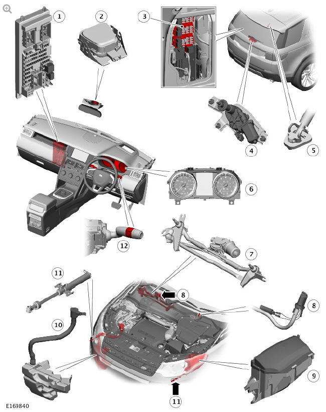
- Central Junction Box (CJB)
- Rain/light sensor
- Rear Junction Box (RJB)
- Rear window wiper motor
- Rear window washer jet
- Instrument Cluster (IC)
- Windshield wiper motor and linkage assembly
- Windshield washer jet
- Engine Junction Box (EJB)
- Windshield washer reservoir
- Headlamp washer jet (2 off)
- Right steering wheel switchpack
OVERVIEW
Windshield wiper and washer operation is controlled by the Central Junction Box (CJB) in response to driver inputs and if fitted, signals from the rain/light sensor.
The wiper and washer system comprises:
- Windshield wiper motor and linkage assembly
- Windshield washer jets - located in cowl panel
- Rear window wiper motor
- Rear window washer jet - located in rear spoiler
- Headlamp washer (if fitted)
- Rain/light sensor (if fitted).
The windshield wipers have five operational states:
- Intermittent wipers - vehicles without rain/light sensor
- Automatic wipers - vehicles with rain/light sensor - automatic wipers can be disabled to operate as intermittent via the Instrument cluster (IC) menu.
- Flick wipe
- Windshield wash and wipe
- Slow wipe
- Fast wipe.
The rear window wiper has three operational states as follows:
- Rear window wash and wipe
- Intermittent rear window wipe
- Continuous rear window wipe.
A windshield washer reservoir contains washer fluid which is used by both the front and rear wipers and the headlamp washers (if fitted).
The headlamp washers (if fitted) use a dedicated headlamp washer pump located in the reservoir. The front and rear washers share a single washer pump.
On vehicles with a rain/light sensor, the wipers have an 'Auto' function. The 'Auto' function uses an output from the rain/light sensor to the CJB on a Local Interconnect Network (LIN) bus to provide automatic operation of the windshield wipers. The rain/light sensor is mounted on the inner surface of the windshield and transmits infra-red light to determine the amount of water on the outer surface of the windshield.
DESCRIPTION
- Windshield Wiper Motor and Linkage Assembly - Description
- Rear Window Wiper and Motor - Description
- Windshield Washer Reservoir - Description
- Headlamp Washers - Description
- Rain/Light Sensor (If Fitted) - Description
- Wipers and Washers Control Switch - Description
- Windshield Wiper Fast/Slow/Single Wipe - Operation
- Rear Window Wiper - Operation
- Headlamp Washers - Operation
READ NEXT:
 Windshield Wiper Motor and Linkage Assembly - Description
Windshield Wiper Motor
NOTE:
Right Hand Drive (RHD) wiper assembly shown
Electrical connector
Electric windshield wiper motor
The windshield wiper motor comprises a 12V electric motor and gear w
Rear Window Wiper and Motor - Description
Rubber mounting (3 off)
Pivot
Motor assembly
Electrical connector
The single speed rear window wiper motor is mounted on the inner panel of
the tailgate and is secured with three bolts. Three
Windshield Washer Reservoir - Description
Windshield washer supply hose
Rear window washer supply hose
Washer fluid level sensor
Right headlamp washer supply hose
Headlamp washer pump
Front/rear washer pump
Left headlamp washer supp
SEE MORE:
The navigation system
Navigation instruction is by map and turn
information displayed on the Touch screen
and can be complemented by voice
guidance, if required. The system uses
signals from Global Positioning System
(GPS) satellites, combined with information
from vehicle sensors and from data stored
on the SD card, to
Speed Control Switches
Vehicles with standard speed control
Vehicles with adaptive speed control
Set speed '+' switch (Engage speed control/increase speed)
Resume 'RES' (Resume previous set speed)
Set speed '-' switch (Decrease speed)
Cancel 'CAN' (Disengage speed control)
Time gap decrease switch (Vehicles wi
