Land Rover Discovery: Antenna
COMPONENT LOCATION
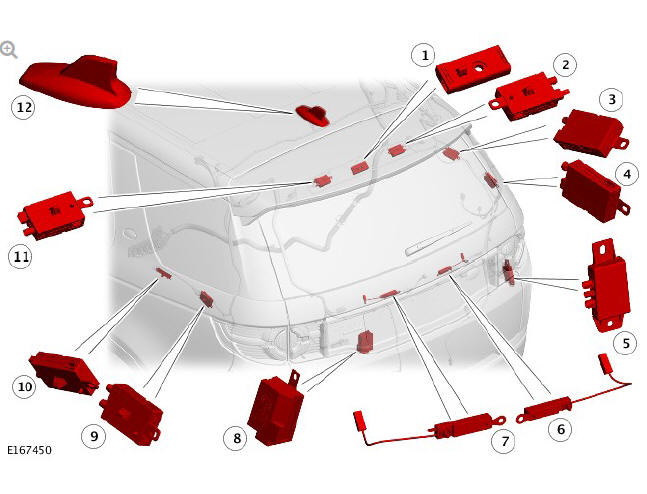
- Radio Frequency (RF) filter
- Amplitude Modulation (AM)/Frequency Modulation (FM) antenna amplifier
- Television (TV) antenna amplifier
- TV antenna amplifier
- Global Positioning System (GPS) signal splitter
- Left Heated Rear Window (HRW) RF filter
- Right HRW RF filter
- RF filter - rear wiper motor relay
- TV antenna amplifier
- TV antenna amplifier/Fuel Fired Booster Heater (FFBH) receiver
- FM/Traffic Message Channel (TMC) / DAB-III antenna amplifier
- Roof pod
OVERVIEW
A number of antennas are used for the various frequency reception requirements of the infotainment system.
A rood pod is fitted and contains antenna for satellite radio, digital radio, mobile communications and GPS.
The Heated Rear Window elements are utilized for AM and FM and DAB reception.
Elements in the rear quarter windows receive RF transmissions for television and Fuel Fired Booster Heater (FFBH).
DESCRIPTION
ROOF POD
A roof pod is fitted externally at the rear of the roof panel. The roof pod is secured to the roof panel with two studs, a mounting bracket and two nuts.
A seal between the roof pod and the outer surface of the roof panel prevents the ingress of water.
The roof pod can contain antenna for:
- Global Positioning system (GPS) or Global Navigation Satellite System (GNSS)
- Digital radio - DAB-3 or DAB-L
- Satellite Digital Audio Radio Service (SDARS) - NAS markets only
- Global System for Mobile (GSM)
- WiFi.
Depending on vehicle specification and market requirements, the roof pod is available with a combination of the above antenna options.
TAILGATE ANTENNAS
The Heated Rear Window (HRW) elements are utilised for Radio Frequency (RF) reception. Two antenna amplifiers are located in the tailgate, above the rear window. Both amplifiers are attached to the upper tailgate panel with a screw and connected to the HRW elements.
The right side antenna amplifier is used for AM/FM reception. The left side antenna amplifier is used for FM reception, Traffic Message Channel (TMC) when navigation system if fitted and DAB-III reception.
REAR QUARTER WINDOW ANTENNAS
The left and right rear quarter windows contain bonded elements for RF reception.
The left rear quarter window contains metallic elements which are bonded to the glass. The elements provide for RF reception for Televison (TV) and Fuel fired Booster Heater (FFBH) remote control.
Two antenna amplifiers are located below the left rear quarter window and connected to the window elements. The forward antenna amplifier is for TV and the rearward antenna amplifier is the Fuel Fired Booster Heater (FFBH) receiver.
The right rear quarter window has bonded metallic elements for TV transmission reception. Two TV antenna amplifiers are located below the window and are connected to the window elements.
RF FILTERS
An RF filter is located centrally in the tailgate, above the rear window. The RF filter is used to remove interference which could be created when the High Mounted Stop Lamp (HMSL) is operated.
Two wavetrap RF filters are located in the tailgate below the rear window.
The RF filters are connected to the positive and negative connection for the HRW and remove interference created when the HRW is operating.
An RF filter is located in the tailgate, below the rear window. The RF filter is used to remove interference from the rear wiper relay.
GLOBAL POSITIONING SYSTEM (GPS) SIGNAL SPLITTER
The GPS signal splitter is located in the right side of the luggage compartment below the right rear quarter window. The GPS signal splitter is only fitted to vehicles with the Telematics system.
The GPS signal splitter shares the GPS signal from the roof pod antenna with the Telematics Control Module and the IAM.
For additional information, refer to: Telematics (415-01, Description and Operation).
OPERATION
DIAGNOSTICS
The Audio Head Unit (AHU) and the Integrated Audio Module (IAM) can detect the connections between the tuners in the IAM and the AM/FM/DAB antenna amplifiers. Faults in these connections will store a Diagnostic Trouble Code (DTC) in the AHU or IAM.
The Television Control Module (TVCM) can detect the connections between the tuners in the TVCM and the TV antenna amplifiers.
The satellite radio (NAS only), the Digital Audio Broadcast (DAB) 3 and Lband and the GPS antennas are monitored by the AHU or the IAM and faults in these antennas will record DTCs.
CONTROL DIAGRAM
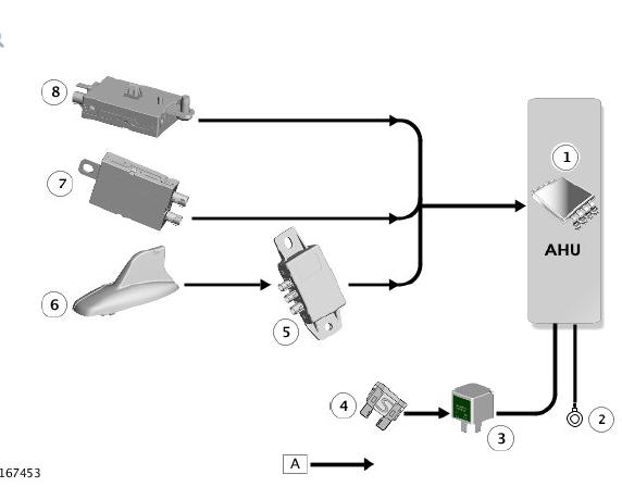
CONTROL DIAGRAM - INCONTROL TOUCH SYSTEMS
- Audio Head Unit (AHU)
- Ground
- Relay - located in Quiescent Current Control Module (QCCM)
- Fuse - located in QCCM
- GPS signal splitter - only on vehicles with Telematics system
- Roof pod - GPS antenna / DAB-L antenna
- FM / TMC / DAB-III antenna amplifier
- AM / FM antenna amplifier
CONTROL DIAGRAM - INCONTROL TOUCH PLUS AND INCONTROL TOUCH PLUS WITH MERIDIAN SURROUND SYSTEMS - ROW
- Integrated Audio Module (IAM)
- Ground
- Relay - located in Quiescent Current Control Module (QCCM)
- Fuse - located in QCCM
- FM / TMC / DAB-III antenna amplifier
- AM / FM antenna amplifier
- Television Control Module (TVCM)
- Digital Radio Control Module (DRCM) or Satellite Radio Control Module (SRCM) - SDARS NAS Only
CONTROL DIAGRAM - INCONTROL TOUCH PLUS AND INCONTROL TOUCH PLUS WITH MERIDIAN SURROUND SYSTEMS - JAPAN ONLY
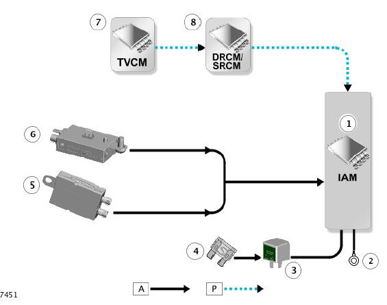
- Integrated Audio Module (IAM)
- Ground
- Relay - located in Quiescent Current Control Module (QCCM)
- Fuse - located in QCCM
- FM / Traffic Message Channel (TMC) / DAB-III antenna amplifier
- AM / FM antenna amplifier
- Television Control Module (TVCM)
- Digital Radio Control Module (DRCM)
- Navigation Control Module (NCM) - If fitted
READ NEXT:
 Component location - Incontrol touch/ Incontrol plus
COMPONENT LOCATION - INCONTROL TOUCH - 6 SPEAKER AUDIO SYSTEM
Front right bass speaker
Front right tweeter speaker
Rear right bass speaker
Roof pod
Antenna amplifier FM/DAB-III
Radio Frequenc
Audio System - Overview
The audio system is available in five versions. Three of the systems use an
Audio Head Unit (AHU) and two use an Integrated Audio Module (IAM).
All systems are controlled using an 8" Touch Screen (TS
SEE MORE:
Wheels and Tires - Tire
Pressure Monitoring
System Locsync
NOTES:
This document describes the fault diagnosis to establish what the
fault is with the TPMS system.
The majority of TPMS faults, are not faults, but low pressure
warnings, indicating the tires have lost air, and have reached the
point where the TPMS ISO light has been illuminated.
There i
Climate Control Air
Conditioning Compressor - Ingenium I4 2.0l
Diesel
(G1885406)/ Removal and
Installation
REMOVAL
Disconnect the battery ground cable.
Refer to: Specifications (414-01 Battery, Mounting and Cables,
Specifications).
WARNING:
Make sure to support the vehicle with axle stands.
Raise and support the vehicle.
Refer to: Air Conditioning System Recovery, Evacuation and
Charging - INGENIUM
