Land Rover Discovery: Audio System / Operation
MEDIA ORIENTED SYSTEMS TRANSPORT (MOST) - INCONTROL TOUCH PLUS AUDIO SYSTEM AND INCONTROL TOUCH PLUS WITH MERIDIAN SURROUND AUDIO SYSTEM ONLY
The components of the audio/infotainment systems are connected on the Media Oriented Systems Transport (MOST) ring. The MOST ring is a fiber optic communications bus for multimedia applications. Audio and control information is transmitted around the MOST ring and is received up by any of the system modules. For example, radio station tuning/selection input by the vehicle user into the Touch Screen (TS) is transmitted on the MOST ring and received by the Integrated Audio Module (IAM) which then selects the requested radio station.
MOST technology uses a plastic optical fiber which forms a network connecting the audio and multimedia system components. Each module in the MOST ring is connected to the plastic optical fiber through a device known as a Fiber Optical Transceiver (FOT). Each FOT has two optical connections; one connection is sensitive to light and is the input, the second connection forms the light source and is the output. The system operates by connecting the output from one FOT to the input of another FOT.
The light signals are sent in one direction only and are created in the following way:
- Electrical signals are converted into an electrical current
- The current then drives a Light Emitting Diode (LED) in the FOT to produce a high intensity red light
- The LED transmits the light through a fiber optic cable
- A photo diode in the FOT at the opposite end of the fiber optic cable detects the light.
The following modules may be connected to the MOST ring dependent on the vehicle equipment level:
- Integrated Audio Module (IAM)
- Touch Screen (TS)
- Digital Radio control module (DRCM)
- Satellite Radio Control Module (SRCM) - NAS only
- Audio Amplifier Module (AAM)
- Rear Seat Entertainment (RSE) control module
- Television Control Module (TVCM)
- Navigation Control Module (NCM) - Japan only
- MOST diagnostic connector.
MOST is a synchronous network. A timing master supplies the clock information and all other devices on the network synchronize their operation to this clock. The timing master for the MOST network on this vehicle is the TS. This TS controls and manages the MOST ring and the system components. An Optical Bus tester to be used in conjunction with approved Land Rover diagnostic equipment to diagnose the MOST system.
The optical bus tester emits a visible, high intensity red light which can be connected into the MOST ring at any point to test the MOST ring integrity.
Disconnecting a MOST connector will reveal if the high intensity red light is visible. If a break occurs in the MOST ring, fault codes are stored in the TS which can be retrieved using approved Land Rover diagnostic equipment.
CONTROL DIAGRAM
CONTROL DIAGRAM - MOST RING
NOTE:
P = MOST
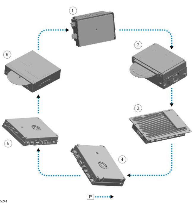
- Touch Screen (TS)
- Integrated Audio Module (IAM)
- Audio Amplifier Module (AAM)
- Digital Radio Control Module (DRCM) or Satellite Radio control Module (SCRM) - NAS only
- Television Control Module (TVCM)
- Navigation Control Module (NCM) - Japan only
CONTROL DIAGRAM - INCONTROL TOUCH AUDIO SYSTEMS
NOTE:
A = Hardwired; I = Composite Voltage Baseband Signal (CVBS); AT = Universal Serial Bus (USB); AU = APIX2
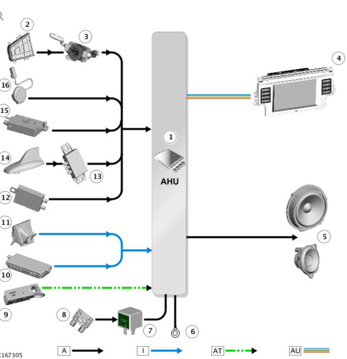
- Audio Head Unit (AHU)
- Left steering wheel switchpack
- Clockspring
- Touch Screen (TS)
- Vehicle speakers
- Ground
- Relay - located in Quiescent Current Control Module (QCCM)
- Fuse - located in QCCM
- Portable audio interface panel
- Camera Control Module (CCM)
- Rear view camera
- FM / TMC / DAB-III antenna amplifier
- GPS signal splitter - if fitted
- Roof pod - Global Positioning System (GPS) antenna / DAB-L antenna
- Amplitude Modulation (AM)/FM antenna amplifier
- Microphone
CONTROL DIAGRAM - INCONTROL TOUCH PLUS AND INCONTROL TOUCH PLUS WITH MERIDIAN SURROUND AUDIO SYSTEMS
NOTE:
A = Hardwired; P = MOST; AE = LVDS; AT = Universal Serial Bus (USB)
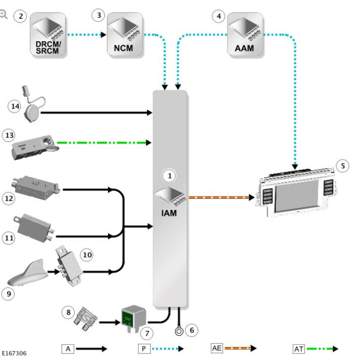
- Integrated Audio Module (IAM)
- Digital Radio Control Module (DRCM) or Satellite Radio Control Module (SRCM) - NAS only
- Navigation Control Module (NCM) - Japan only
- Audio Amplifier Module (AAM)
- Touch Screen (TS)
- Ground
- Relay - located in Quiescent Current Control Module (QCCM)
- Fuse - located in QCCM
- Roof pod - Global Positioning System (GPS) antenna / DAB-L antenna
- GPS signal splitter - if fitted
- FM / TMC / DAB-III antenna amplifier
- Amplitude Modulation (AM)/FM antenna amplifier
- Portable audio interface panel
- Microphone
READ NEXT:
 Audio Unit (G1785533) / Removal and Installation
REMOVAL
CAUTION:
Use a suitable trim tool.
NOTE:
Removal steps in this procedure may contain installation details.
Disconnect the battery ground cable.
Refer to: Specifications (414-01 Battery, Mount
Cellular Phone
COMPONENT LOCATION - INCONTROL TOUCH AUDIO SYSTEMS
Microphone
Audio Amplifier Module (AAM)
Audio Head Unit (AHU)
Touch Screen (TS)
COMPONENT LOCATION - INCONTROL TOUCH PLUS AND INCONTROL TOUCH
Diagnosis and Testing Cellular Phone
PRINCIPLE OF OPERATION
For a detailed description of the Mobile phone system and operation, refer
to the relevant Diagnosis and Testing section of the workshop manual.
REFER to: (415-01 Information a
SEE MORE:
Intelligent stop/start
The Intelligent stop/start system is
designed to improve fuel efficiency and
is automatically activated when the
vehicle's ignition is switched on. Unless it
is required to support other vehicle
systems, the engine will switch off if the
vehicle is stopped, for example, at traffic
lights. When the b
Diagnosis and Testing Information and Entertainment System/ Symptom chart
SYMPTOM:
Audio/video system
inoperative at start up
POSSIBLE CAUSES:
Last used audio/video
source inoperative
MOST network fault
ACTION
GO to Pinpoint Test A.
SYMPTOM:
Audio/video soft key
greyed out on touch
screen
POSSIBLE CAUSES:
Last used audio/video
source ino
