Land Rover Discovery: Diagnosis and Testing Telematics
The complexities of the electronics involved with the telematics system, of which the GPS antenna and navigation display are parts, and the multiplexed communication network which are connected to it preclude the use of workshop general electrical test equipment. Therefore, reference should be made to the approved Jaguar Land Rover diagnostic system for detailed instructions on testing the telematics system unit.
The approved Jaguar Land Rover diagnostic system tests and analyses all functions of the vehicle telematics system and the various systems affected by it.
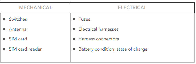
Where a fault is indicated, some basic diagnostic methods may be necessary to confirm that connections are good and that wiring is not damaged before installing a new component.
PRINCIPALS OF OPERATION
For a detailed description of the telematics system, refer to the relevant description and operation section of the workshop manual.
REFER to: Telematics (415-01 Information and Entertainment System, Description and Operation).
INSPECTION AND VERIFICATION
CAUTION:
Diagnosis by substitution from a donor vehicle is NOT acceptable.
Substitution of control modules does not guarantee confirmation of a fault, and may also cause additional faults in the vehicle being tested and/or the donor vehicle
- Verify customer concern.
- Visually inspect for obvious signs of damage and system integrity.
Visual Inspection
- If an obvious cause for an observed or reported concern is found, correct the cause (if possible) before proceeding to the next step.
- If the cause is not visually evident check the system for any logged diagnostic trouble codes (DTCs) and proceed to the DTC index.
- Check DDW for open campaigns. Refer to the corresponding bulletins and SSMs which may be valid for the specific customer complaint and carry out the recommendations as required.
Telematics system diagnosis Do's and Don'ts
Below are a list of DO's and DON'Ts, which should be adhered to in conjunction with any workshop literature or manuals.
DO:
- Ensure that all actions, routines and symptoms are recorded with the date and time, as this aids any subsequent off-board investigations.
- Capture screenshots of any concerns and/or error messages that are presented in the smartphone app or customer portal.
- Have the vehicle engine running when completing manual actions such as a long bCall press.
- Try and have the vehicle in an area of good mobile network coverage. Use a mobile phone as a comparison tool to check this.
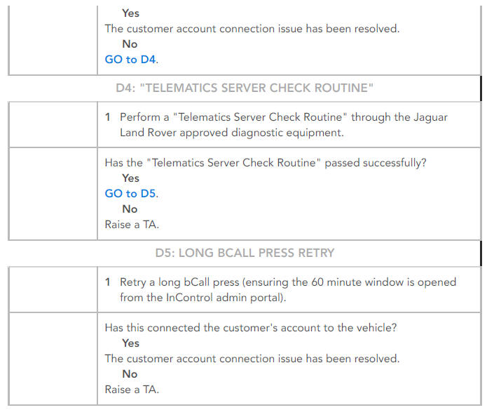
- Repeat the "Telematics Server Check Routine" using the Jaguar Land Rover approved diagnostic equipment. Due to the variable factors that can affect the telematics system, it is advisable that any "Telematics Server Check Routines" are ran multiple times at any given troubleshooting point. Up to 5 attempts should be sufficient for the service to make viable communication attempts over the server.
DON'T
- Use a telematics control module from another vehicle during diagnosis and troubleshooting. This causes severe issues within the off-board database.
- Replace the telematics control module in the event that you are unable to diagnose a concern. You must raise a TA for further investigation.
- Do not attempt to remove the customer's account from the vehicle if the account has been linked but they are unable to complete the activation process.
- Hand a vehicle over if the PDI process has failed, as this means that the eCall/bCall service is not activated and will not work in the event of the vehicle airbags being deployed or the eCall button being pressed.
- Hand a vehicle over before it has been registered to the new owner.
Telematics control module replacement
A telematics control module replacement should only be carried out after all other troubleshooting and diagnosis steps have been taken (including raising a TA for further assistance) AND has been approved by Retailer Technical Services. You should not perform a telematics control module replacement in the hope it will resolve a concern that you cannot diagnose.
During the "TCU Replacement Routine", essential information relating to the new unit is sent to the Jaguar Land Rover off-board database, therefore it is crucial that the telematics control module replacement routine is ran in full.
- Physically fit the telematics control module as instructed in the Workshop Manual.
- Ensure the Jaguar Land Rover approved diagnostic equipment has been updated to the latest version.
- Don't use a "dongle" or an older version of the Jaguar Land Rover approved diagnostic equipment.
- Run the "TCU Replacement Routine" via the Jaguar Land Rover approved diagnostic equipment in an area with good signal.
Raising a telematics related Technical Assistance (TA) - Minimum standards
When raising a Technical Assistance (TA), it is essential that as much information as possible is captured and documented on the TA. This will save valuable time when the relevant teams investigate. You should aim to provide:
- The time and date the concern was first experienced.
- The time and date of all Jaguar Land Rover approved diagnostic equipment routines that have been ran.
- The time and date of all manual actions performed e.g. long bCall press, smartphone app login etc.
- The timestamp of "Last vehicle contact" - This is obtained from the bottom of the home screen in the smartphone app.
- In the situation where a telematics control module replacement has been carried out, should provide the serial number of the old module and the serial number of the new module as well as the time, date and the outcome of the telematics control module "Replacement Routine".
- Confirmation of any DTC's that have been recorded and whether these have been resolved and/or cleared.
- The current illumination status of both the eCall and bCall buttons.
- A screenshot or an exact text copy of any error messages shown in the smartphone app
- Attach the latest session file
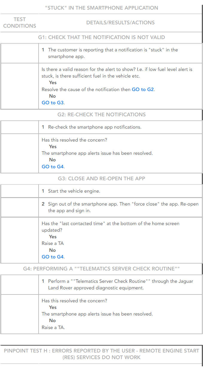
SYMPTOM CHART - TELEMATICS ERROR MESSAGES SHOWN IN THE INSTRUMENT CLUSTER
Error message "SOS Limited Functionality" shown in the instrument cluster
NOTE:
The clearing of this message can only be achieved by resolving a hardware issue.
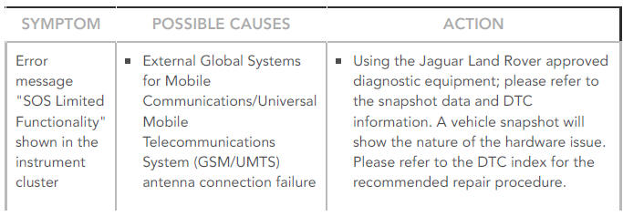
SYMPTOM:
Error message "SOS Limited Functionality" shown in the instrument cluster
POSSIBLE CAUSES:
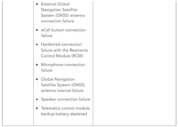
- External Global Systems for Mobile Communications/Universal Mobile Telecommunications System (GSM/UMTS) antenna connection failure
- External Global Navigation Satellite System (GNSS) antenna connection failure
- eCall button connection failure
- Hardwired connection failure with the Restraints Control Module (RCM)
- Microphone connection failure
- Global Navigation Satellite System (GNSS) antenna internal failure
- Speaker connection failure
- Telematics control module backup battery depleted
ACTION
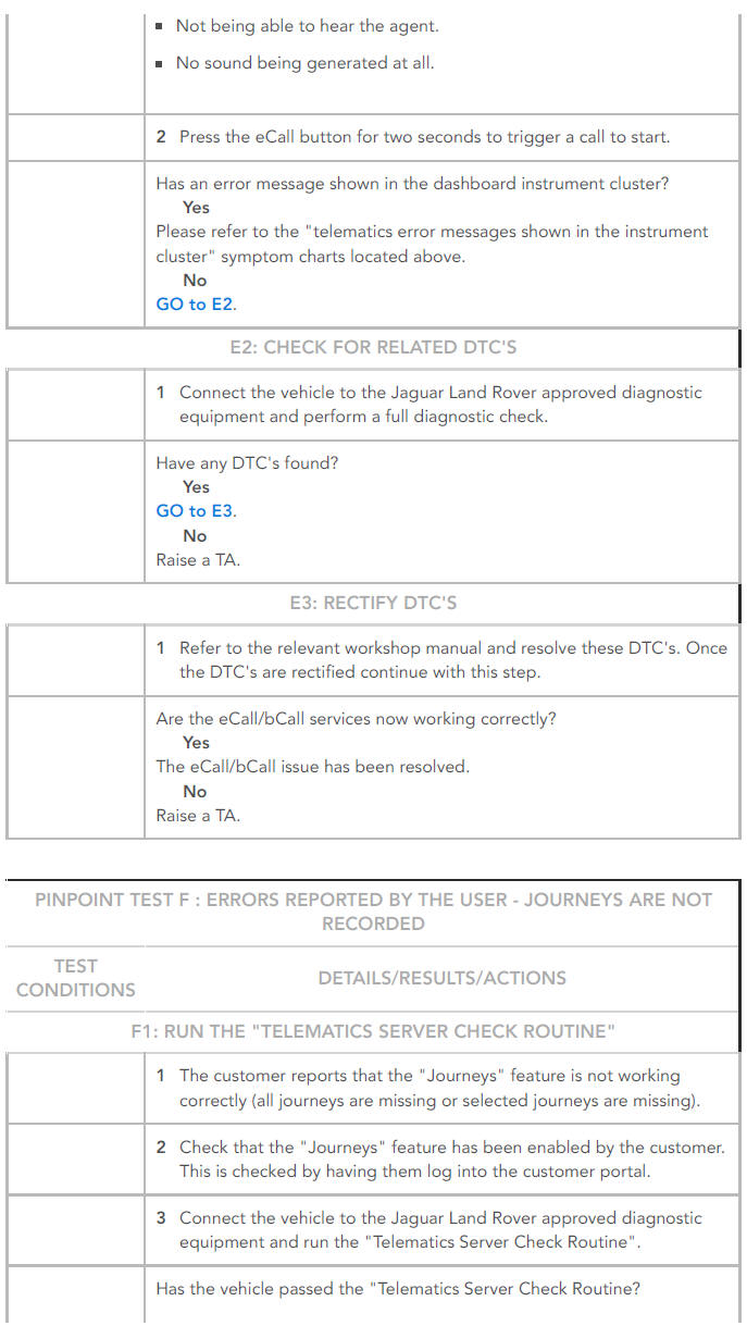
Using the Jaguar Land Rover approved diagnostic equipment; please refer to the snapshot data and DTC information. A vehicle snapshot will show the nature of the hardware issue.
Please refer to the DTC index for the recommended repair procedure.
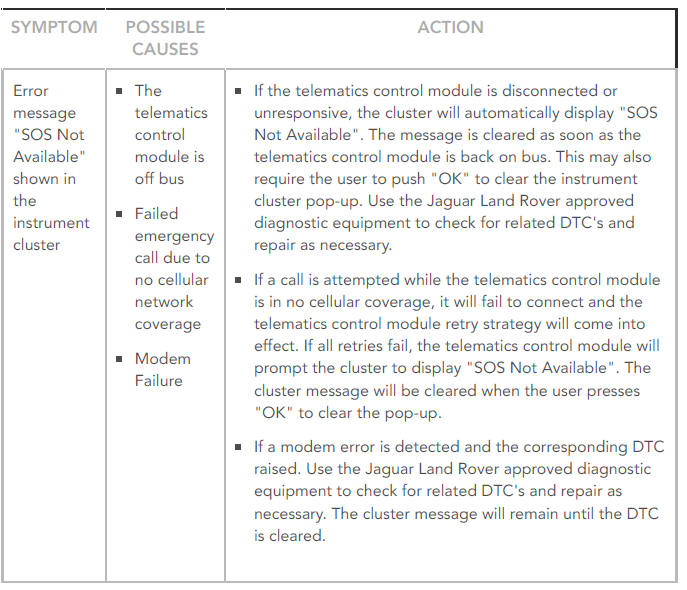
Symptom Chart - Error message "SOS not available" shown in the instrument cluster
Please note that this list is not extensive and full diagnosis should always be carried out as per the workshop literature.
SYMPTOM CHART
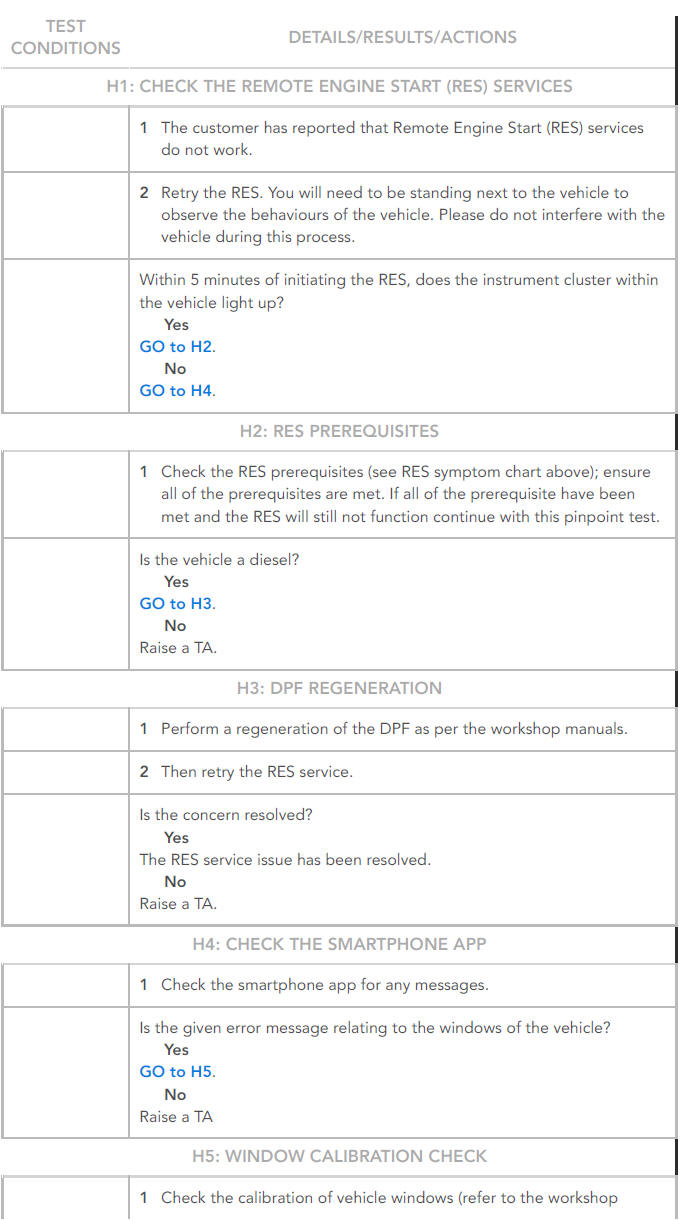
Symptom Chart - Remote Engine Start (RES) prerequisites
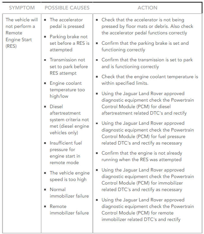
SYMPTOM:
The vehicle will not perform a Remote Engine Start (RES)
POSSIBLE CAUSES:
- The accelerator pedal is pressed
- Parking brake not set before a RES is attempted
- Transmission not set to park before RES attempt
- Engine coolant temperature too high/low
- Diesel aftertreatment system criteria not met (diesel engine vehicles only)
- Insufficient fuel pressure for engine start in remote mode
- The vehicle engine speed is too high
- Normal immobilizer failure
- Remote immobilizer failure
ACTION:
- Check that the accelerator is not being pressed by floor mats or debris. Also check the accelerator pedal functions correctly
- Confirm that the parking brake is set and functioning correctly
- Confirm that the transmission is set to park and is functioning correctly
- Check that the engine coolant temperature is within specified limits.
- Using the Jaguar Land Rover approved diagnostic equipment check the Powertrain
- Control Module (PCM) for diesel aftertreatment related DTC's and rectify
- Using the Jaguar Land Rover approved diagnostic equipment check the Powertrain
- Control Module (PCM) for fuel pressure related DTC's and rectify as necessary
- Confirm that the engine is not already running when the RES was attempted
- Using the Jaguar Land Rover approved diagnostic equipment check the Powertrain
- Control Module (PCM) for immobilizer related DTC's and rectify as necessary
- Using the Jaguar Land Rover approved diagnostic equipment check the Powertrain
- Control Module (PCM) for remote immobilizer related DTC's and rectify
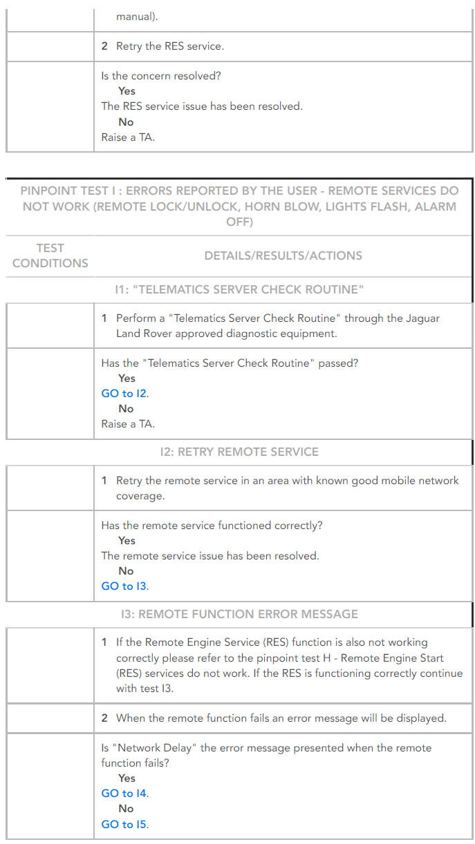
Symptom Chart - Smartphone app theft notification trigger types
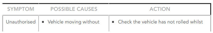
SYMPTOM:
Unauthorised movement alert
POSSIBLE CAUSES:
- Vehicle moving without the engine running
ACTION:
- Check the vehicle has not rolled whilst parked. Check the vehicle transmission is in park with the parking brake applied
SYMPTOM:
The vehicle alarm has been triggered
POSSIBLE CAUSE:
- Unauthorised tampering with the vehicle
ACTION:
Check that the vehicle has not been tampered with whilst parked and the vehicle alarm is functioning correctly
SYMPTOM:
Battery disconnect
POSSIBLE CAUSE:
Vehicle battery is disconnected
ACTION:
- Check the wiring and connections to the vehicle battery. Using the Jaguar Land Rover approved diagnostic equipment check for related DTC's and repair as necessary
SYMPTOM:
GPS tamper
POSSIBLE CAUSE:
- The Global Positioning System(GPS) antenna disconnected
ACTION:
- Check the wiring and connections to the GPS antenna. Using the Jaguar Land Rover approved diagnostic equipment check for related DTC's and repair as necessary
SYMPTOM:
GSM tamper
POSSIBLE CAUSE:
- The Global Systems for Mobile Communications (GSM) antenna is disconnected
ACTION:
- Check the wiring and connections to the GSM antenna. Using the Jaguar Land Rover approved diagnostic equipment check for related DTC's and repair as necessary
SYMPTOM:
GSM jamming
POSSIBLE CAUSE:
- Attempts to block Global Systems for Mobile Communications (GSM) signal using a device or alternative method
ACTION:
- Check that the GSM antenna is functioning correctly. Using the Jaguar Land Rover approved diagnostic equipment check for related DTC's and repair as necessary
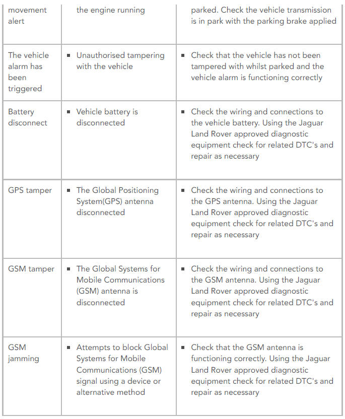
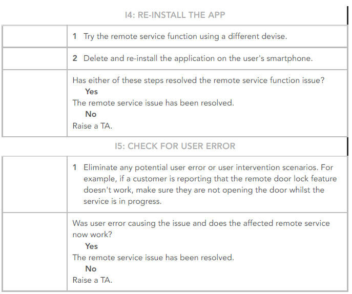
PINPOINT TESTS
NOTES:
- In ALL cases, prior to performing a test eCall, please notify the customer as they may be contacted by the Police or other service providers.
- If you successfully connect to an operator during an eCall or bCall test, you MUST advise them that you are performing a test or diagnosis of the service.
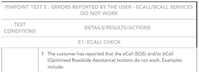
DTC Index
For a complete list of all diagnostic trouble codes (DTCs) that could be logged on this vehicle, please refer to Section 100-00.
REFER to: Diagnostic Trouble Code Index - DTC: Telematic Control Module (TCU) (100-00 General Information, Description and Operation).
READ NEXT:
 Front Door Speaker (G1785139) / Removal and Installation
REMOVAL
NOTES:
Removal steps in this procedure may contain installation details.
RH illustration shown, LH is similar.
Refer to: Front Door Trim Panel (501-05 Interior Trim and
Ornamentation, Remo
General Information Incontrol Touch Software Update
ACTIVATION
NOTES:
The following must be adhered to when updating the software level
of the InControl Touch Audio Head Unit (AHU).
When attempting to update the software level on the InControl
Tou
Information and Entertainment System / General
information
Map Update Applicability - Digital Versatile Disc (DVD) / Universal Serial Bus (USB) Flash Drive / Secure Digital (SD) Memory Card
NOTE:
For vehicles using a Navigation Control Module (NCM), ref
SEE MORE:
Exhaust - Ingenium i4 2.0l Diesel Diesel Particulate Filter - Vehicles
Without- Diesel Exhaust Fluid (G1887685) / Removal Installation
REMOVAL
WARNING:
Observe due care when working near a hot exhaust system.
NOTE:
Removal steps in this procedure may contain installation details.
WARNING:
Make sure to support the vehicle with axle stands.
Raise and support the vehicle.
Torque: 55 Nm
Torque: 10 Nm
Torque: 6 Nm
CAUTION:
Make su
Seating - Operation
FRONT SEAT ADJUSTMENT - NON-MEMORY SEATS
The driver and passenger seat switchpacks each receive a permanent fused
primary battery power supply from the Central Junction Box (CJB). This
feed is always live regardless of ignition power mode status.
Each switch provides a ground and power supply to th
