Land Rover Discovery: Electric Cooling Fan

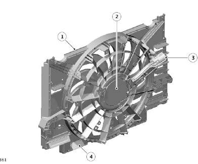
- Fan shroud
- Cooling fan motor
- Electrical connection
- Speed flaps
An electric, variable speed cooling fan is installed in a shroud attached to the rear of the radiator. The cooling fan is operated by an electric cooling fan control module, integrated into the electric motor, under the control of the ECM via a PWM signal. An electrical connector at the right side of the shroud provides the interface between the cooling fan harness and the vehicle wiring.
The electric cooling fan control module is provided with:
- A battery power supply from the engine junction box (EJB)..
- An ignition signal from the ECM relay in the EJB.
- A PWM signal from the ECM.
- A ground.
The ECM varies the PWM signal to the fan control module between 0 and 100% to operate the fan motor in one of four modes:
- Off
- Minimum speed (750 rev/min).
- Linear variable speed between minimum and maximum speeds.
- Maximum speed (2820 rev/min).
Under hot operating conditions, the electric cooling fan may continue to operate for up to five minutes after the engine has been switched off.
The system is protected against abnormal internal temperature by measuring its internal temperature at two points with temperature sensors.
- Sensor 1 : This sensor is used to calculate the temperature of active components near the micro controller. The fan will stop immediately if the fan internal temperature reaches 135ºC (275ºF). At motor stop, after a delay of 120 seconds the diagnostic feedback will be sent. Normal operation will resume once the temperature is less than 120ºC (248ºF).
- Sensor 2 : This sensor is used to measure the temperature of the power stage of the PCBA (near the metal oxide semi-conductor field effect transistors (MOSFETs)) to reduce the power if the temperature is too high (derating) and to stop the motor in case of an over temperature condition
The fan will derate if the powerstage internal temperature reaches 135ºC (275ºF) and stop motor function at 145ºC (293ºF). At motor stop, after a delay of 120 seconds the diagnostic feedback will be sent. Normal fan operation will resume once the powerstage temperature falls to 135ºC (275ºF).
COOLANT EXPANSION TANK

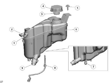
- Pipe connection - coolant expansion line from radiator
- Pipe connection - coolant expansion line from engine thermostat housing
- O-ring seal
- Cap
- Bolt and washer
- Coolant expansion tank
- Location grommet
- Coolant level sensor
- Hose connection to coolant pump
The coolant expansion tank is located in the left side of the engine compartment. The tank is located by a grommet on its underside and positively secured with a bolt and washer to a bracket on the vehicle body and a second bracket that locates in a molded slot in the tank body.
The coolant expansion tank has three connections; one for radiator bleed, one for engine bleed and one for outlet to the thermostat housing.
An engine coolant level sensor is located in the underside of the tank body.
The sensor reacts to the influence of a magnetic field. A float, with integral magnet, is located inside the tank, over the sensor tube. The sensor has contacts inside the tube, which are normally open. When the fluid level reduces, the magnetic float moves down the tube. When the magnet reaches the sensor contacts, the magnetic field closes the contacts. The sensor connects hardwired to the Central Junction Box (CJB) which receives the signals from the sensor. Maximum and minimum marks are molded on the tank body.
The coolant expansion tank provides the following functions:
- Service fill.
- Coolant expansion during warm-up
- Air separation during operation.
- System pressurization by the filler cap.

