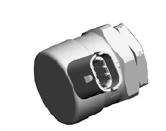
Land Rover Discovery: Fuel Rail Pressure Control Valve (PCV)

The fuel rail Pressure Control Valve (PCV) is located in a threaded port in the rearward end of the fuel rail. The PCV regulates the fuel pressure within the fuel rail and is controlled by the ECM using Pulse Width Modulation (PWM) outputs to the solenoid valve.
When the solenoid is de-energized, an internal spring holds an internal valve closed. At a pre-determined fuel pressure, the force of the internal spring is overcome, opening the valve and allowing fuel pressure to decay into the fuel return pipe. When the pressure in the fuel rail decays to a predetermined pressure, the spring force overcomes the fuel pressure and closes the valve. When the ECM energizes the solenoid, the valve is closed allowing the fuel pressure to build.
The ECM constantly monitors the fuel pressure and activates the fuel rail PCV accordingly to control the fuel rail pressure within the required parameters. Relieved fuel from the fuel rail is directed through the fuel rail return pipe to the low pressure fuel filter return circuit.
The ECM controls the fuel rail pressure by operating the control valve solenoid using a PWM signal. By varying the duty cycle of the PWM signal, the ECM can accurately control the fuel rail pressure and hence the pressure delivered to the injectors according to engine load. This is achieved by the control valve allowing a greater or lesser volume of fuel to pass from the high pressure side of the pump to the un-pressurized fuel return line, regulating the pressure on the HP side.
The fuel rail PCV receives a PWM signal from the ECM of between 0 and 12V. The ECM controls the operation of the control valve using the following information to determine the required fuel pressure
- Fuel rail pressure
- Engine load
- APP sensor position
- Engine coolant temperature
- Engine speed.
In the event of a total failure of the fuel rail PCV, the engine will not start. In the event of a partial failure of the fuel rail PCV, the ECM will activate the solenoid with the minimum PWM duty cycle which results in the injection quantity being limited.
FUEL RAIL PRESSURE (FRP) SENSOR
.jpg)
The Fuel Rail Pressure (FRP) sensor is located in a threaded port in the forward end of the fuel rail.
The FRP sensor measures the fuel pressure in the fuel rail which is supplied from the HP fuel pump.
The FRP sensor is a piezo resistor type sensor. The sensor receives a 5V reference voltage supplied through a resistor within the ECM and produces an analogue signal of between 0 and 5V depending on the pressure sensed.
LP gives a low voltage output and consequently HP gives a higher voltage output. The ECM uses this pressure signal to monitor the fuel pressure in the fuel rail and adjust the HP fuel pump fuel metering valve to control the fuel pressure in the fuel rail.
The ECM monitors the FRP sensor for faults and can store fault related DTC's. These can be retrieved using an approved diagnostic system.

