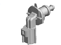
Land Rover Discovery: Fuel Temperature Sensor and Fuel Metering Valve
.jpg)
- Fuel metering valve
- Fuel temperature sensor
Fuel Temperature Sensor
The fuel temperature sensor is located in a threaded port in the HP fuel pump.
The sensor is a NTC sensor which is connected to the ECM by two wires.
The ECM fuel temperature sensor circuit consists of an internal voltage divider circuit which incorporates a NTC thermistor. As the fuel temperature raises the resistance through the sensor decreases. The output from the sensor is the change in voltage as the thermistor allows more current to pass to ground relative to the temperature of the fuel.
The ECM monitors the fuel temperature constantly. If the fuel temperature exceeds a pre-determined threshold, the ECM invokes an engine 'derate' strategy. This reduces the amount of fuel delivered to the injectors in order to allow the fuel to cool. When this occurs, the driver may notice a loss of performance.
The wires to the fuel temperature sensor are monitored by the ECM for short and open circuit. The ECM also monitors the 5V supply. If a failure occurs a fault is recorded in the ECM memory and the ECM uses a default fuel pressure value.
Fuel Metering Valve
The fuel metering valve is located on the top of the HP fuel pump. The valve is sealed to the HP fuel pump body with an O-ring seal and secured with 2 bolts.
The fuel metering valve is a variable position solenoid-operated valve that is controlled by the ECM with a Pulse Width Modulation (PWM) signal.
The valve controls the quantity of fuel delivered to the HP Fuel pump from the fuel pump module in the fuel tank.
The fuel metering valve returns unwanted fuel back to the fuel tank. This avoids unused fuel being pressurized by the HP stage of the pump, only to be returned back to return system by the fuel rail pressure control valve, wasting energy and heating the fuel.
VARIABLE CAMSHAFT TIMING (VCT) SOLENOID
.jpg)
The VCT solenoid is located on the chain cover and secured with 2 screws.
The VCT solenoid is controlled by a Pulse Width Modulation (PWM) output from the ECM. The ECM uses signals from the CMP sensor and determines the position of the VCT actuator which has a direct interface with the exhaust camshaft.
The VCT solenoid incorporates a spindle that acts on the spool valve in the VCT actuator to advance and retard the exhaust camshaft timing.
ENGINE COOLANT TEMPERATURE (ECT) SENSOR - ELECTRIC THERMOSTAT HOUSING
.jpg)
The ECT sensor is located in the electric thermostat housing. The sensor is a sealed in the thermostat housing with an O-ring seal. The sensor is a push fit in the thermostat housing and rotated clockwise to lock in position.
The ECT sensor monitors the engine coolant temperature in the thermostat housing and uses the information to control the electric thermostat.
Operation of the ECT sensor is as described above for the radiator outlet ECT sensor.
ENGINE COOLANT TEMPERATURE (ECT) SENSOR - RADIATOR OUTLET

The ECT sensor is located in the radiator outlet. The sensor is a sealed in the radiator outlet with an O-ring seal. The sensor is a push fit in the radiator outlet and rotated clockwise to lock in position.
The radiator ECT sensor provides the ECM and the IC with engine coolant temperature status.
The ECM uses the temperature information for the following functions:
- Fueling calculations
- Limit engine operation if engine coolant temperature becomes too high
- Cooling fan operation.
The IC uses the temperature information for temperature gauge operation.
The engine coolant temperature signal is transmitted on the HS-CAN powertrain systems bus by the ECM for use by the IC and other systems.
The ECT sensor circuit consists of a voltage divider which incorporates a NTC thermistor within the ECT sensor. The input to the sensor is a 5V reference voltage supplied through a resistor within the ECM. The ground from the sensor is also connected to the ECM which measures the voltage across the sensor. As the engine coolant temperature raises the resistance of the sensor decreases and vice versa. The output voltage from the sensor changes as the thermistor allows more current to pass to ground relative to the temperature of the coolant. The ECM calculates the coolant temperature from a map of sensor voltage against temperature.
The ECM adjusts fuel delivery for the measured engine coolant temperature to ensure optimum driveability at all times. The engine will require more fuel when it is cold to overcome fuel condensing on the cold metal surfaces inside the combustion chamber. To achieve a richer air/fuel ratio, the ECM extends the injector opening time. As the engine warms up the air/fuel ratio is leaned off.
If the ECT sensor fails, the following symptoms may be observed:
- Difficult cold starting
- Difficult hot starting
- Reduced engine performance
- Temperature gauge inoperative or inaccurate reading.
In the event of an ECT sensor signal failure, the ECM applies a default value of 60 ºC (140 ºF) engine coolant temperature for fueling purposes.

