
Land Rover Discovery: Headlamp bulb replacement
Land Rover Discovery (2009–2016) Owner's Manual / Maintenance / Headlamp bulb replacement
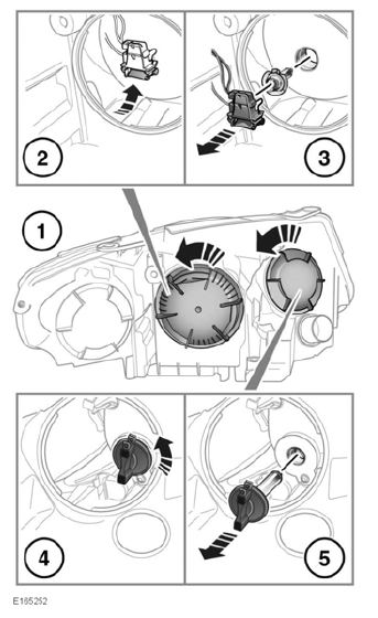
- At the back of the headlamp unit, rotate the appropriate bulb cover counter-clockwise and then lightly pull to remove it.
- Remove the low beam bulb holder from the headlamp.
- Unclip the low beam bulb and remove it from the bulb holder.
- Rotate the DRL/high beam bulb unit counter-clockwise.
- Remove the DRL/high beam bulb unit from the headlamp housing.
Reverse the removal procedure to install a bulb holder/bulb unit.
Note: Note the orientation of any removed components to aid refitting.
DIRECTION INDICATOR BULB REPLACEMENT
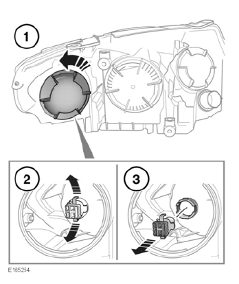
To gain more room for accessibility, follow the process for removing the headlamp unit
- At the back of the headlamp unit, rotate the appropriate bulb cover counter-clockwise and then lightly pull to remove it.
- Release the sides of the bulb holder.
- Pull the holder to remove it from the headlamp and access the indicator bulb.
Reverse the removal procedure to install a bulb holder/bulb unit.
Note: For Xenon headlamp units, the bulb cover for the direction indicator is located on the inboard side.
Note: Note the orientation of any removed components to aid refitting.


READ NEXT:
 Rear direction indicator and reversing lamp bulb replacement
Replacing a rear direction indicator:
Remove the appropriate loadspace
vent door.
Rotate the rear lamp's retaining screw
counter-clockwise, until fully released
and then remove. This allows th
Wipers service position
To avoid damage to the bonnet, do
not lift the wiper blades when they
are in the normal parked position.
Note: The Smart key must remain in the
vehicle while the wiper blades are
replaced.
Before chan
SEE MORE:
Engine - Ingenium i4 2.0l Diesel Engine Mount Alignment (G1815586) / General
Procedures
ADJUSTMENT
Transmission mounting
WARNING:
Do not work on or under a vehicle supported only by a jack.
Always support the vehicle on safety stands.
Raise and support the vehicle.
Using a suitable hydraulic jack, support the transmission.
CAUTION:
Take extra care when installing the component.
Rear Suspension Rear
Wheel Bearing (G1818219)
/ Removal and Installation
SPECIAL TOOL(S)
GENERAL EQUIPMENT
REMOVAL
NOTES:
Some variation in the illustrations may occur, but the essential
information is always correct.
Some components shown removed for clarity.
WARNING:
Do not work on or under a vehicle supported only by a jack.
Always support the vehicle on s
© 2019-2026 Copyright www.lrdisc.com
