Land Rover Discovery: Intake Air Distribution and Filtering - Ingenium i4 2.0l Diesel / Description and Operation
COMPONENT LOCATION
.jpg)
- Intake manifold
- Turbocharger
- Clean air duct
- Exhaust Gas Recirculation (EGR) valve
- Air cleaner
- Dirty air duct
- Charge air cooler
- Electric throttle
OVERVIEW
The intake air distribution and filtering system comprises of:
- Air cleaner assembly
- Turbocharger
- Charge air cooler
- Intake manifold
- Manifold absolute pressure and temperature (MAPT)sensor.
For additional information, refer to: Electronic Engine Controls (303-14B Electronic Engine Controls - INGENIUM I4 2.0L Diesel, Description and Operation).
- Mass air flow (MAF) sensor.
For additional information, refer to: Electronic Engine Controls (303-14B Electronic Engine Controls - INGENIUM I4 2.0L Diesel, Description and Operation).
The system cleans, cools and compresses the intake air. The turbocharger compresses the air which is then cooled in the charge air cooler before being mixed with the injected fuel in the cylinder producing a high energy combustion increasing engine performance.
DESCRIPTION
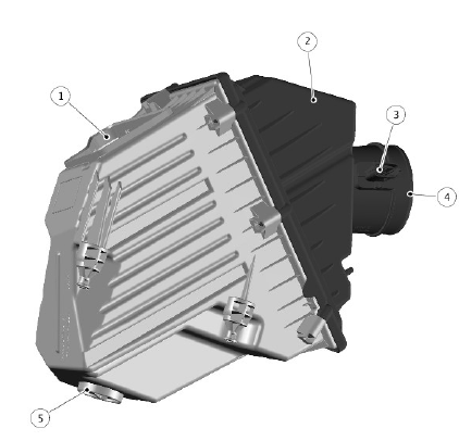
AIR CLEANER

- Dirty air duct connection
- Lid
- Mass Air Flow (MAF) Sensor
- Clean air duct connection
- Drain valve
The air cleaner assembly is located on the front left side of the engine compartment. The air cleaner consists of a base, lid, MAF sensor, air filter element to trap particulates and a drain valve to prevent the accumulation of water within the air cleaner housing.
The porous dirty air duct clips into the air cleaner base and is secured to the body with push-in type retainers.
The air outlet connection of the air cleaner incorporates a MAF sensor. The sensor is connected to the Engine Control Module (ECM).
The output of the MAF sensor is required by the ECM to ensure the correct amount of fuel and air is delivered to the cylinders.
For additional information, refer to: Electronic Engine Controls (303-14B Electronic Engine Controls - INGENIUM I4 2.0L Diesel, Description and Operation).
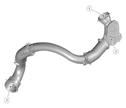
CLEAN AIR DUCT
.jpg)
- Clean air duct inlet
- Clean air duct outlet
The clean air duct transfers air from the air cleaner outlet to the compressor intake on the turbocharger through the Exhaust Gas Recirculation (EGR) valve.
The clean air duct is secured to the MAF sensor with a hose clamp. The clean air duct outlet is secured to the EGR mounting plate with three bolts.
The clean air duct transfers air from the air cleaner to the EGR Valve.
For additional information, refer to: Engine Emission Control (303-08B Engine Emission Control - INGENIUM I4 2.0L Diesel, Description and Operation).
CHARGE AIR DUCT - HOT

- Charge air duct inlet
- Resonator
- Charge air duct outlet
The charge air duct interconnects the turbocharger compressor outlet and the charge air cooler.
To reduce air induction noise, the charge air duct incorporates a resonator.
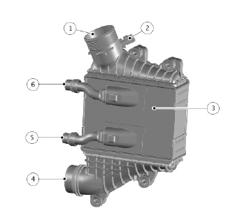
CHARGE AIR COOLER

- Air outlet
- Charge air temperature sensor
- Charge air cooler
- Air intake
- Coolant outlet
- Coolant inlet
The charge air cooler is located at the front of the engine compartment.
The turbocharger is designed to force more air mass into the engine intake manifold and combustion chambers.
This compression process by the turbocharger produces heat which can reduce the performance gains of turbocharging due to reduced density of the intake air and an increase in the cylinder combustion temperature.
To counteract this the charge air cooler is used to reduce the intake air temperature which increases the density of the air allowing more air molecules to be delivered to the combustion chamber.
The lower connection is the inlet for the compressed air delivered from the turbocharger compressor. The upper connection is the outlet for the cooled compressed air to be delivered by the electric throttle to the intake manifold.
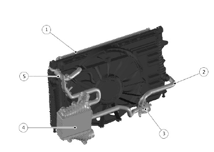
CHARGE AIR COOLER COOLING COMPONENTS

- Low temperature circuit radiator
- Low temperature circuit outlet hose
- Coolant pump - charge air cooler
- Charge air cooler
- Low temperature circuit inlet hose
A separate low temperature coolant circuit, equipped with an air-to-water heat exchanger, provides charge air cooling in combination with an electrical coolant pump.
Intake manifold air temperature is used as a reference for activating the charge air cooling circuit. After this target temperature is achieved, the intake manifold air temperature is regulated by activating the charge air cooling pump.
The charge air cooler has a stand alone cooling circuit with its own radiator, pump and pipe work. The only connection to the main cooling circuit is a pipe from the inlet hose to the top of the main high temperature cooling circuit radiator via a T-piece. The T-piece has a bleed screw on the top of it, which is used to fill and bleed the system.
The charge air cooler has a temperature sensor which provides a signal to the ECM.
The pump is controlled by a pulse width modulation (PWM) signal from the ECM.
The pump receives a supply from the engine junction box (EJB).
INTAKE MANIFOLD
.jpg)
- Manifold Absolute Pressure and Temperature (MAPT) Sensor
- Inlet manifold
- Electric throttle
The intake manifold is attached to the cylinder head. The electric throttle is secured to the intake manifold.
The MAPT sensor is mounted on the intake manifold.
The output of the MAPT sensor is required by the ECM to ensure the correct amount of air is delivered to the cylinders.
For additional information, refer to: Electronic Engine Controls (303-14B Electronic Engine Controls - INGENIUM I4 2.0L Diesel, Description and Operation).
The ECM controls the electric throttle using a PWM signal to ensure the correct amount of air is delivered to the intake manifold.
OPERATION
Ambient air is drawn into the intake air system through the dirty air duct located above the left front wheel, under the hood. The air passes through the duct and into the bottom of the air cleaner assembly. The air is filtered through a pleated paper filter to remove particulate matter. The clean air from the filter passes through a tube in the air cleaner damper chamber and passes through a MAF sensor before entering the clean air duct to the turbocharger.
The MAF sensor measures the air flow into the turbocharger and engine.
At the turbocharger the clean air is compressed by the turbine compressor impeller. The hot, compressed air is passed from the turbocharger through a hose to the charge air cooler. The air is cooled which increases it density and passes from the charge air cooler to the electric throttle which controls the amount of air entering the intake manifold.
The electric throttle is controlled by the ECM which controls the position of the throttle butterfly valve to allow the correct amount of air into the intake manifold. A MAPT sensor, located in the intake manifold, measures the air pressure in the manifold and is used by the ECM in conjunction with the MAF sensor, located in the air filter, to calculate pressure and density of the air entering the engine.
INPUT/ OUTPUT DIAGRAM
.jpg)
A = HARDWIRED; AL = PULSE WIDTH MODULATION (PWM)
- ECM
- Electric Throttle
- Ground
- Supply
- Ambient Air Temperature sensor (AAT)
- Mass Air Flow (MAF) sensor
- Charge air cooler temperature sensor
- Manifold Absolute Pressure and Temperature (MAPT) sensor

