Land Rover Discovery: Manual Transmission - Transaxle External Controls Gearshift Lever (G1781378) / Removal and Installation
Land Rover Discovery (2009–2016) Service Manual / Powertrain / Manual Transmission Transaxle
and Clutch / Manual Transmission - Transaxle
External Controls
Gearshift Lever (G1781378)
/ Removal and Installation
REMOVAL
NOTES:
- Removal steps in this procedure may contain installation details.
- Some variation in the illustrations may occur, but the essential information is always correct.
NOTE:
Neutral must be selected before the cables are released to allow the cables to be correctly set on the install.
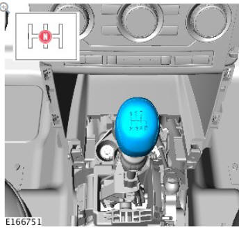
Refer to: Floor Console (501-12 Instrument Panel and Console, Removal and Installation).
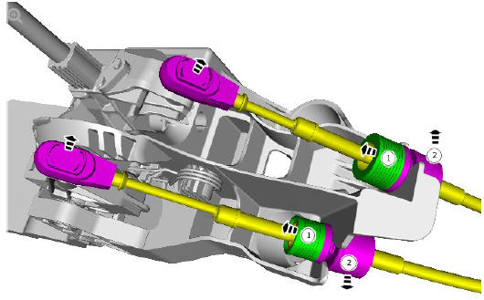
- Release the locking ring.
- Release the gear selector cable.
.jpg)
INSTALLATION
- To install, reverse the removal procedure.
- Refer to: Gearshift Cable Adjustment (308-00 Manual Transmission/Transaxle and Clutch - General Information, General Procedures).
Manual Transmission - Transaxle External Controls Gearshift Lever Knob (G1781379) / Removal and Installation
REMOVAL
NOTES:
- Removal steps in this procedure may contain installation details.
- Some variation in the illustrations may occur, but the essential information is always correct.
WARNING:
The selector knob will be released suddenly, keep face clear during removal.
.jpg)
CAUTIONS:
- Carefully release either side of the component to avoid damage.
- Do not disassemble further if the component is removed for access only.
.jpg)
INSTALLATION
- To install, reverse the removal procedure.
READ NEXT:
 Manual Transmission - Transaxle
External Controls
Gearshift Linkage (G1781377)
/ Removal and Installation
Manual Transmission - Transaxle
External Controls
Gearshift Linkage (G1781377)
/ Removal and Installation
REMOVAL
NOTES:
Removal steps in this procedure may contain installation details.
Some variation in the illustrations may occur, but the essential
information is always correct.
CAUTION:
Make sure
Manual Transmission - Transaxle
External Controls
/ Description and Operation
COMPONENT LOCATION
Selector lever knob
Selector lever
Selector lever housing
Selector lever cables
OVERVIEW
The manual transmission external controls comprise a selector lever
assembly and two
SEE MORE:
Lower Control Arm and
Tie Bar
Flag nut retaining screw
Flag nut - lower control arm to wheel knuckle
Bush - lower control arm to wheel knuckle
Bolt - lower control arm to wheel knuckle
Lower control arm
Bolt (front) - lower control arm to subframe
Bush (front) - lower control arm to subframe
Bush (rear) - lower contro
Front end Sheet Metal
Repairs Fender
Apron Panel
Front Section (G1775681)
- Installation
Installation
Dress flanges where necessary.
Remove the spot welds from the new fender apron panel as
indicated.
Carefully separate the fender apron panel from the reinforcement.
Mark, measure and cut the new fender apron panel reinforcement
as indicated.
Offer up the new fender apron
© 2019-2026 Copyright www.lrdisc.com
