Land Rover Discovery: Rear Suspension Spring (G1774680) / Removal and Installation
GENERAL EQUIPMENT
.jpg)
REMOVAL
CAUTION:
Do not remove the rubber isolators form the spring. A new spring is installed with the correct isolators.
NOTES:
- Some variation in the illustrations may occur, but the essential information is always correct.
- Some components shown removed for clarity.
- Removal steps in this procedure may contain installation details.
WARNING:
Do not work on or under a vehicle supported only by a jack.
Always support the vehicle on safety stands.
Raise and support the vehicle.
Refer to: Wheel and Tire (204-04, Removal and Installation).
.jpg)
.jpg)
General Equipment: Transmission jack
WARNING:
Use two suspension spring compressors located on opposite sides of the spring. Make sure the suspension spring compressors are correctly installed. Refer to manufactures instructions.
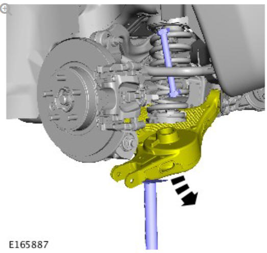
.jpg)
General Equipment: Suspension Spring Compressor
NOTE:
Make sure that a new bolt is installed.
.jpg)
Torque: 170 Nm
NOTE:
Make sure that a new nut and bolt are installed.
.jpg)
Torque:
Stage 1: 40 Nm
Stage 2: 180º
NOTE:
Make sure that a new nut and bolt are installed.
.jpg)
Torque:
Stage 1: 40 Nm
Stage 2: 60º
NOTE:
Make sure that a new bolt is installed.
.jpg)
Torque:
Stage 1: 40 Nm
Stage 2: 180º
General Equipment: Transmission jack
INSTALLATION
CAUTIONS:
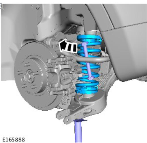
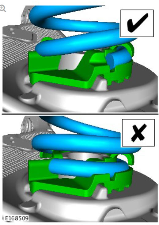
- Make sure to install the spring and isolator in the correct position.
- Nuts and bolts must be tightened with vehicle at normal ride height.
To install, reverse the removal procedure.
Refer to: Specifications (204-00, Specifications).
READ NEXT:
 Rear Suspension Toe
Link (G1774720) / Removal and
Installation
Rear Suspension Toe
Link (G1774720) / Removal and
Installation
PART(S)
REMOVAL
NOTES:
Some variation in the illustrations may occur, but the essential
information is always correct.
Removal steps in this procedure may contain installation details.
Refer to:
Rear Suspension Wheel
Knuckle (G1775239) / Removal
SPECIAL TOOL(S)
PART(S)
REMOVAL
CAUTIONS:
Nuts and bolts must be tightened with the weight of the vehicle on
the suspension.
Do not allow halfshafts to hang unsupported at one end or joint
dam
SEE MORE:
Driveshaft - Ingenium I4 2.0l Diesel, Vehicles without- active Driveline
(G1890849) - Removal
PART(S)
REMOVAL
NOTE:
Some variation in the illustrations may occur, but the essential
information is always correct.
WARNING:
Make sure to support the vehicle with axle stands.
Raise and support the vehicle.
Refer to: Exhaust System (309-00C Exhaust System - INGENIUM I4
2.0L Diesel, Removal and In
Using the parking aid
Parking aid switch. Located next to the
Touch screen.
Parking aid sensor detection zones.
360º Park Distance Control sensor
detection zones.
Parking aid and 360º Park
Distance Control sensors will not
detect moving objects, such as
children and animals, until they
are dangerously close. A
