Land Rover Discovery: Rear Window Wiper Pivot Arm (G1780367) / Removal and Installation
Land Rover Discovery (2009–2016) Service Manual / Body / Wipers and washers / Rear Window Wiper Pivot Arm (G1780367) / Removal and Installation
REMOVAL
NOTE:
Removal steps in this procedure may contain installation details.
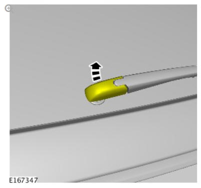
NOTE:
Make sure that this component is installed to the noted removal position.
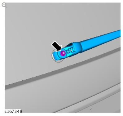
Torque: 5.4 Nm
NOTE:
Do not disassemble further if the component is removed for access only.
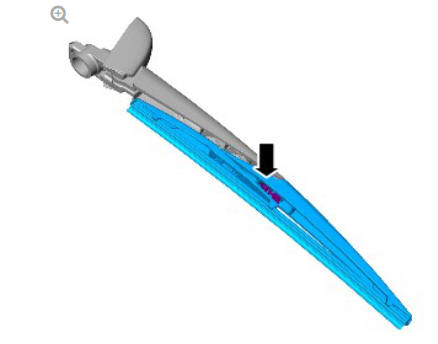
INSTALLATION
To install, reverse the removal procedure.
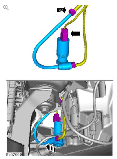
Windshield washer pump (G1780364) removal and installation
REMOVAL
NOTE:
Removal steps in this procedure may contain installation details.
WARNING:
Make sure to support the vehicle with axle stands.
Raise and support the vehicle.
NOTE:
Right side only.
Refer to: Fender Splash Shield (501-02, Removal and Installation).
CAUTION:
Be prepared to collect escaping fluids.
INSTALLATION
To install, reverse the removal procedure.
READ NEXT:
 Windshield Washer Reservoir (G1780365) / Removal and Installation
REMOVAL
WARNING:
Make sure to support the vehicle with axle stands.
Raise and support the vehicle.
Refer to: Front Bumper Cover (501-19, Removal and Installation).
Torque: 5 Nm
Torque: 4.1 Nm
To
Wiper Pivot Arm (G1780362) / Removal and Installation
REMOVAL
NOTES:
Removal steps in this procedure may contain installation details.
LHD illustration shown, RHD is similar.
CAUTION:
Note the installed position of the component prior to
removal.
Wipers and Washers
COMPONENT LOCATION
Central Junction Box (CJB)
Rain/light sensor
Rear Junction Box (RJB)
Rear window wiper motor
Rear window washer jet
Instrument Cluster (IC)
Windshield wiper motor and link
SEE MORE:
Television Control Module (TVCM)
Connectors - TV Antenna amplifiers
CVBS connector - Output to Touch Screen (TS)
LVDS connector - Output to RSECM
Connector - MOST
Connector - 12V power supply from Battery Junction Box (BJB)
and ground
The TVCM is located below the front left seat and is attached
to a bracket
adjacent to
Information and Entertainment Display (G1785534) / Removal and
Installation
REMOVAL
CAUTION:
Use a suitable trim tool.
NOTE:
Removal steps in this procedure may contain installation details.
Disconnect the battery ground cable.
Refer to: Specifications (414-01 Battery, Mounting and Cables,
Specifications).
Refer to: Floor Console Upper Section (501-12 Instrument Panel
and
© 2019-2026 Copyright www.lrdisc.com
