Land Rover Discovery: Side Panel Sheet Metal Repairs Side Panel (G1770901) - Installation
Land Rover Discovery (2009–2016) Service Manual / Body / Body Repairs and General
Information / Side Panel Sheet
Metal Repairs
Side Panel (G1770901) / Side Panel Sheet
Metal Repairs
Side Panel (G1770901)
- Installation
Installation
NOTE:
Make sure that a zinc rich primer is applied to any bare metal surfaces.
- Dress the flanges where necessary
- Clean and prepare the panel surfaces.
CAUTION:
This step requires the aid of another technician as the side panel is heavy.
- Offer up the new side panel and clamp into position. Check alignment, if correct, proceed to next step, if not, rectify and recheck before proceeding.
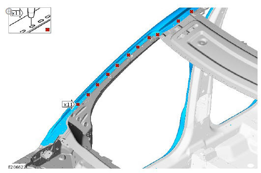
NOTE:
Follow steps 1 and 2 as shown to cut the MIG braze slots.
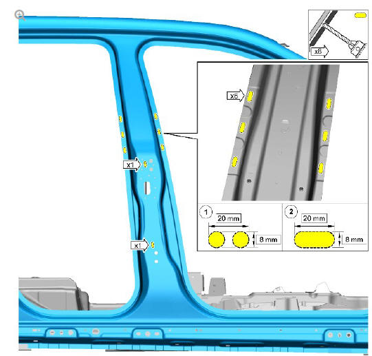
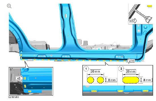
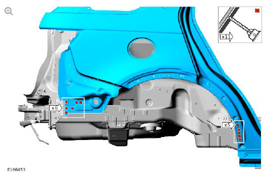
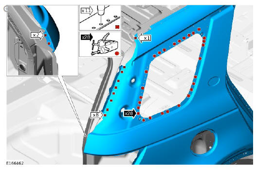
- Mark the position and cut slots in the new side panel where the Metal Inert Gas (MIG) braze slot welds are to be installed as indicated.
NOTE:
Follow steps 1 and 2 as shown to cut the MIG braze slots.
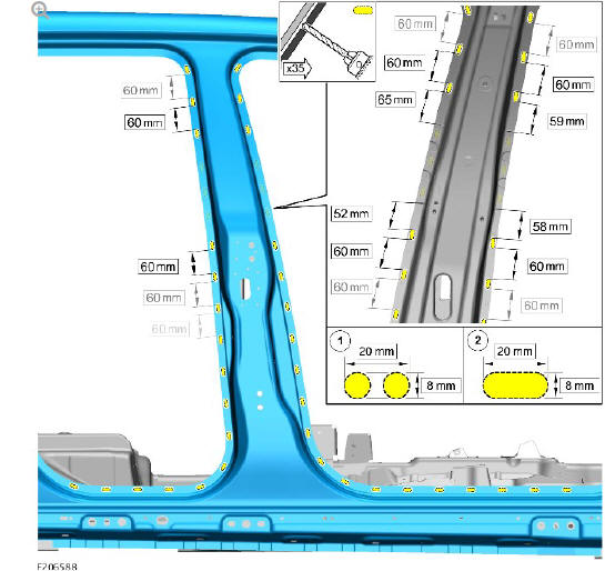
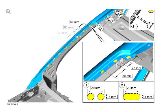
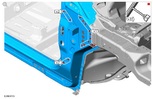
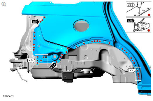
- Mark the position and cut slots in the new side panel where the MIG braze slot welds are to be installed as indicated.
NOTE:
Follow steps 1 to 3 as shown to cut the MIG braze slots.
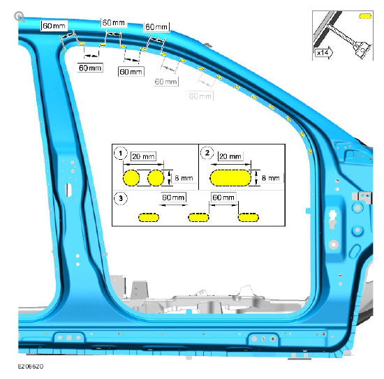
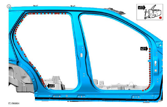
- Mark the position and cut slots in the new side panel where the MIG braze slot welds are to be installed as indicated.
NOTE:
Follow steps 1 to 3 as shown to cut the MIG braze slots.
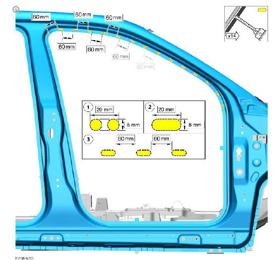
- Mark the position and cut slots in the new side panel where the MIG braze slot welds are to be installed as indicated.
NOTE:
Follow steps 1 and 2 as shown to cut the MIG braze slots.
- Mark the position and cut slots in the new side panel where the MIG braze slot welds are to be installed as indicated.
NOTE:
Follow steps 1 and 2 as shown to cut the MIG braze slots.
- Mark the position and cut slots in the new side panel where the MIG braze slot welds are to be installed as indicated.
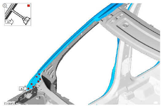
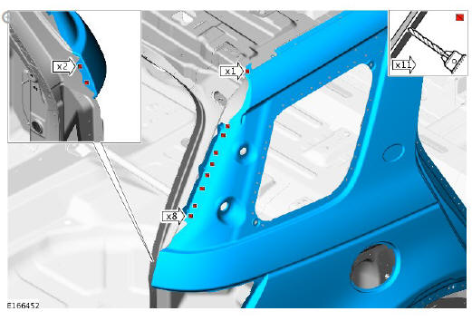
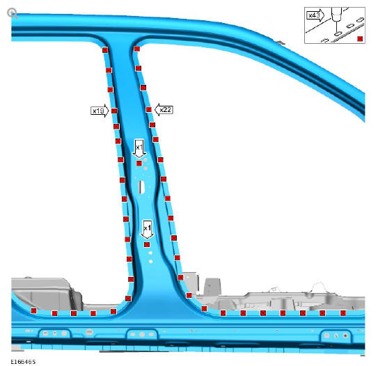
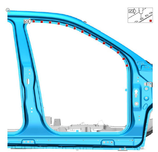
- Drill holes in the new side panel where the MIG plug welds are to be installed as indicated.
- Drill holes in the new side panel where the MIG plug welds are to be installed as indicated.
- Drill holes in the new side panel where the MIG plug welds are to be installed as indicated.
- Drill holes in the new side panel where the MIG plug welds are to be installed as indicated.
CAUTION:
This step requires the aid of another technician as the side panel is heavy.
- Remove the side panel.
- Deburr the drilled slots and holes.
- Clean and prepare the panel surfaces.
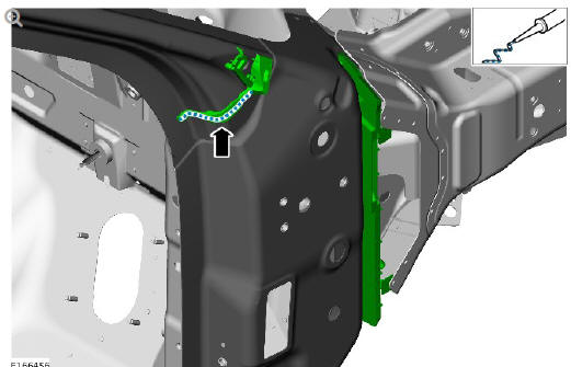
- Apply a 5 mm bead of Land Rover recommended sealer to the Noise, Vibration and Harshness (NVH) components as indicated.
- Apply a 5 mm bead of Land Rover recommended sealer to the NVH components as indicated.
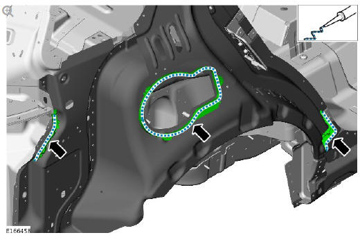
- Apply a 5 mm bead of Land Rover recommended sealer to the NVH components as indicated.
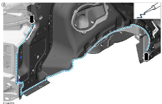
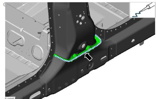
- Apply a 5 mm bead of Land Rover recommended sealer to the vehicle assembly as indicated.
CAUTION:
This step requires the aid of another technician as the side panel is heavy.
- Offer up the new side panel and clamp into position. Check alignment, if correct, proceed to next step, if not, rectify and recheck before proceeding.
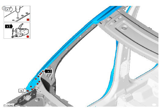
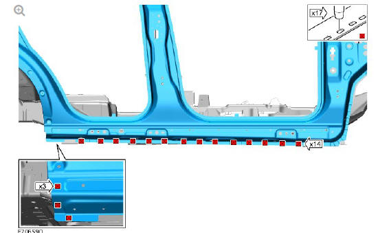
- Install the spot and MIG plug welds as indicated.
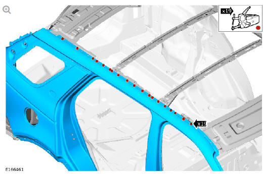
- Install the spot welds as indicated.
- Install the spot and MIG plug welds as indicated.
- Install the spot and MIG plug welds as indicated.
- Install the spot welds as indicated.
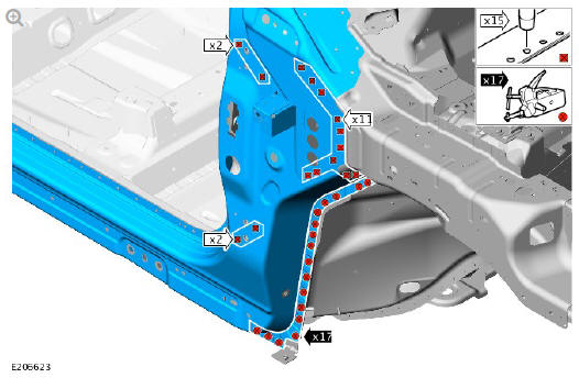
- Install the spot and MIG plug welds as indicated.
- Install the MIG braze slot welds as indicated.
- Install the MIG braze slot welds as indicated.
- Install the MIG braze slot welds as indicated.
- Install the MIG braze slot welds as indicated.
- Dress all welded joints.
- Apply a Land Rover recommended sealer and seal the panel flange edges of the MIG braze slot welds in the door aperture areas to prevent water ingress.
- Make sure that any open or exposed panel joints are correctly sealed.
- Make sure corrosion protection is applied to all areas affected by repair.
- The installation of associated panels and components is the reversal of removal procedure.
READ NEXT:
 Side Panel Sheet
Metal Repairs
Rocker Panel and 'B'
Pillar Outer
Panel (G1770927) -
Removal
Side Panel Sheet
Metal Repairs
Rocker Panel and 'B'
Pillar Outer
Panel (G1770927) -
Removal
NOTE:
The rocker panel and B-pillar outer is installed in conjunction with:
Front bumper cover
Front fender
Front fender splash shield
Front door
Rear door
Front seat
Rear seat cushion
Cowl s
Side Panel Sheet
Metal Repairs
Rocker Panel and 'B'
Pillar Outer
Panel (G1770927) -
Installation
Installation
Dress the flanges where necessary.
Using the old rocker panel and B-pillar outer for reference measure,
mark and cut the new rocker panel and B-pillar outer where the
Metal Inert Gas
SEE MORE:
Body Closures Front
Door (G1785716)/ Removal and Installation
REMOVA L
NOTES:
Removal steps in this procedure may contain installation details.
Some variation in the illustrations may occur, but the essential
information is always correct.
Disconnect the battery ground cable.
Refer to: Specifications (414-01 Battery, Mounting and Cables,
Specifications
Supplemental Restraint System
Driver Airbag
Module (G1785722) / Removal and
Installation
REMOVAL
WARNINGS:
Do not probe supplemental restraint system (SRS) electrical
connectors.
To avoid accidental deployment and possible personal injury,
the
backup power supply must be depleted before repairing or
replacing any air bag supplemental restraint system (SRS)
components. To deplet
© 2019-2026 Copyright www.lrdisc.com
