Land Rover Discovery: Audio System / Description
TOUCH SCREEN (TS)
Touch Screen - Audio Head Unit - InControl Touch Audio Systems
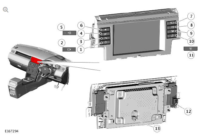
- Infotainment system On/Off switch
- 'Camera' switch
- 'Parking Aid' On/Off switch (if fitted)
- 'General Settings'
- 'Park Assist' switch
- 'Home Menu' switch
- 'Mode' switch
- 'Media System' switch
- 'Telephone System' switch
- 'Audio Settings' switch
- 'Navigation' switch
- Connector - Touch screen switchpack
- Connector - Touch screen
The 8 inch 800 X 480 resolution, single view Touch Screen (TS) is located in the center of the instrument panel. The TS comprises an 8 inch color, touch sensitive display, with a TS switchpack located on either side.
The TS switchpack differs depending on system specification; for example, if parking aid or navigation are specified on the vehicle, these switches will replace 'Audio Settings' or 'Mute' functions respectively. The functions can still be accessed via the home menu using the TS.
The TS is the primary user interface of the audio system. It communicates with the other components of the audio/infotainment system on the medium speed Controller Area Network (CAN) comfort systems and allows control of the audio system and other system functions from a single point.
No configuration procedure is required if the TS or TS switchpacks are replaced.
Calibration of the TS using approved Land Rover diagnostic equipment enables updates to be downloaded as new technology becomes available or any fault concerns require software updates.
The rear of the TS has a single 6 pin connector for power, ground and APIX2 connections.
The TS switchpack comprises 8 switches. The function of the switches can differ dependant on the infotainment system installed in the vehicle.
The TS switchpack has a single 12 pin connector which provides electrical connections to and from the switches. The connector provides switch power supplies, switch illumination supplies and output from the switches via a resistive ladder. The outputs from the Parking Aid and Park Assist switches are passed directly to the Parking Aid Control Module (PACM).
Touch Screen - Integrated Audio Module - InControl Touch Plus Audio Systems
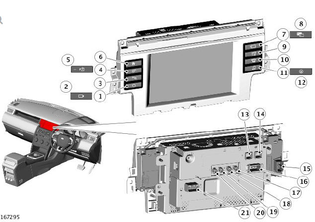
- Infotainment system On/Off switch
- 'Camera' switch
- 'Parking Aid' On/Off switch (if fitted)
- 'General Settings'
- 'Park Assist' switch
- 'Home Menu' switch
- 'Mode' switch
- 'Single' or 'Dual-View' switch
- 'Media System' switch
- 'Telephone System' switch
- 'Audio Settings' switch
- 'Navigation' switch
- Connector - LVDS input from Integrated Audio Module (IAM) or Navigation control module (Japan or Asia markets)
- Connector - LVDS output to Instrument Cluster (IC)
- Connector - Touch screen switchpack
- Connector - Media Oriented System Transport (MOST)
- Connector - CVBS video input from Parking Aid Control Module (PACM) or rear view camera
- Connector - CVBS video input from Television Control Module (TVCM) or Rear Seat Entertainment Control Module (RSECM)
- Connector - CVBS video input from Integrated Audio Module (IAM)
- Connector - CVBS video output to RSECM
- Connector - power, ground, medium speed CAN comfort systems bus, left steering wheel switchpack input
The 8 inch 800 X 480 resolution, Touch Screen (TS) is located in the center of the instrument panel. The TS comprises an color, touch sensitive display, with a TS switchpack located on either side.
Two versions of the TS are available; single view and dual view. The TS switchpacks differ depending on system specification; for example, if parking aid or navigation are specified on the vehicle, these switches will replace 'Audio Settings' or 'Mute' functions respectively. The functions can still be accessed via the home menu using the TS.
The TS is the Bus Master for the Media Oriented System Transport (MOST) system and contains the timing master for the MOST system.
When the vehicle systems become active the TS is woken up by CAN bus activity and subsequently wakes up the other audio modules via the MOST.
The TS is the primary user interface of the audio system. It communicates with the other components of the audio/infotainment system on the MOST ring and allows control of the audio system and other infotainment systems from a single point. No configuration procedure is required if the TS or TS switchpacks are replaced.
Calibration of the TS using approved Land Rover diagnostic equipment enables updates to be downloaded as new technology becomes available or any fault concerns require software updates.
The rear of the TS has electrical connectors for power, ground, medium speed CAN comfort systems bus, Low Voltage Differential Signalling (LVDS) and Composite Video Baseband Signal (CVBS) video and MOST. The usage of the LVDS and CVBS connectors differs depending on the equipment level of the vehicle.
The TS switchpack comprises 8 switches. The function of the switches can differ dependant on the infotainment system installed in the vehicle.
The TS switchpack has a single 12 pin connector which provides electrical connections to and from the switches. The connector provides switch power supplies, switch illumination supplies and output from the switches via a resistive ladder. The outputs from the Parking Aid and Park Assist switches are passed to the Integrated Control Panel (ICP), where they are converted to medium speed CAN comfort systems signals. The CAN signals are passed from the ICP to the Integrated Audio Module (IAM).
Dual View Touch Screen (TS)
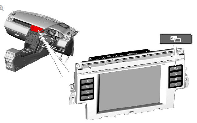
The dual-view TS enables the passenger and driver to view completely different images from their respective seating positions. This technology has provided a solution for the legal issues attached to viewing moving images whilst the vehicle is in motion. It is not possible for the driver to view moving images with an active speed signal, but the passenger can view DVD and TV independent of the driver.
Vehicles fitted with a dual view TS are supplied with a headphone transmitter located in the headliner and one pair of infra-red wireless headphones. This allows the front seat passenger to view and listen to music, DVD and TV without disturbing the driver.
NOTE:
Due to legislation the NAS markets do not receive this option. A single view display is available in these markets.
The dual-view TS uses Parallax Barrier Shutter Technology to alternately hide and reveal columns of pixels to the left and right hand views of the screen. The display comes with a specially designed agar coating to help prevent sunlight bleaching.
To access a TV or video image when the vehicle is in motion and single view is selected, the dual view switch on the TS switchpack should be pressed by either the driver or the passenger. This will then switch the TS to dual-view mode allowing the passenger to view TV or video, but not the driver. A second press of the switch will change the TS back to single view.
Once dual-view has been selected, the driver can change the current screen without affecting the passengers view by the source on the TS.
The audio system can only broadcast one audio source. Therefore, the TV / video source that is current for the passenger will also be the audio the driver can hear. The passenger's can choose to use headphones to listen to the sound source accompanying the TV / video. This allows the driver to listen to a different audio source or navigation commands via the vehicle speaker system.
The driver's view is also event driven, for example, if reverse gear were to be selected, the rear view camera will be displayed automatically, overriding the currently displayed information.
Clock
The CJB contains the master clock functionality. Other vehicle infotainment system modules that require clock functionality use the time supplied from the CJB.
The clock is available to any control module that is connected to an interconnecting bus, for example, any of the CAN buses or the MOST ring.
The clock display is configurable to show in AM / PM or 24 hour format.
Midnight is shown as 12:00AM or 00:00 respectively. The default condition, if not specified, after power on or delivery, should default to 12:00PM or 00:00. Depending upon the market set, the clock will default to either 12 or 24 hour format.
The time is adjusted from the TS. Under conditions when any bus system could be asleep or shut down, the TS does not allow clock adjustments.
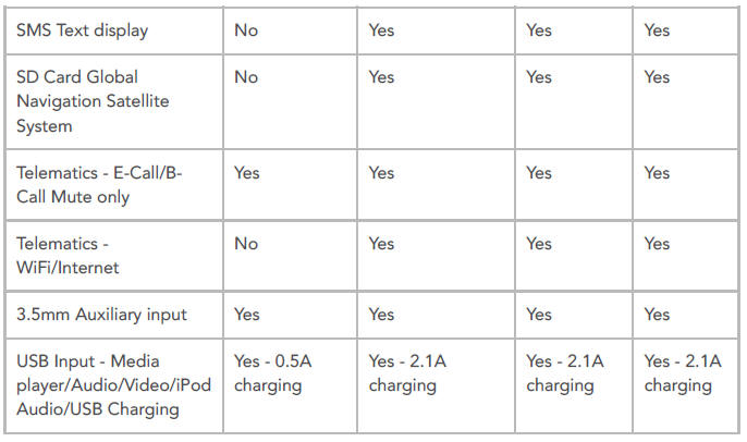
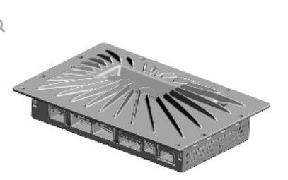
AUDIO HEAD UNIT (AHU) - INCONTROL TOUCH AUDIO SYSTEMS
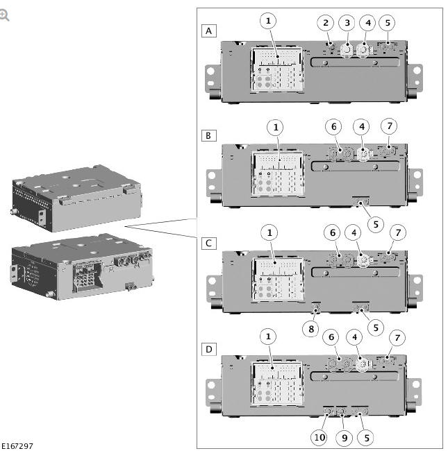
- Level 'B' AHU - All markets
- Level 'C' AHU with navigation - All markets
- Level 'C' AHU with navigation and SDARS - NAS only
- Level 'C' AHU with navigation and DAB - European markets only
- Connector - 40 pin
- Connector - Camera
- Connector - USB
- Connector - Touch Screen APIX2
- Connector - AM/FM antenna input
- Connector - USB
- Connector - GPS and camera
- Connector - SDARS (NAS markets only)
- Connector- DAB-III (European markets only)
- Connector - DAB-L (European markets only)
The Audio Head Unit (AHU) is located in the center of the instrument panel, below the TS.
Four levels of AHU are available depending on market and vehicle
specification: 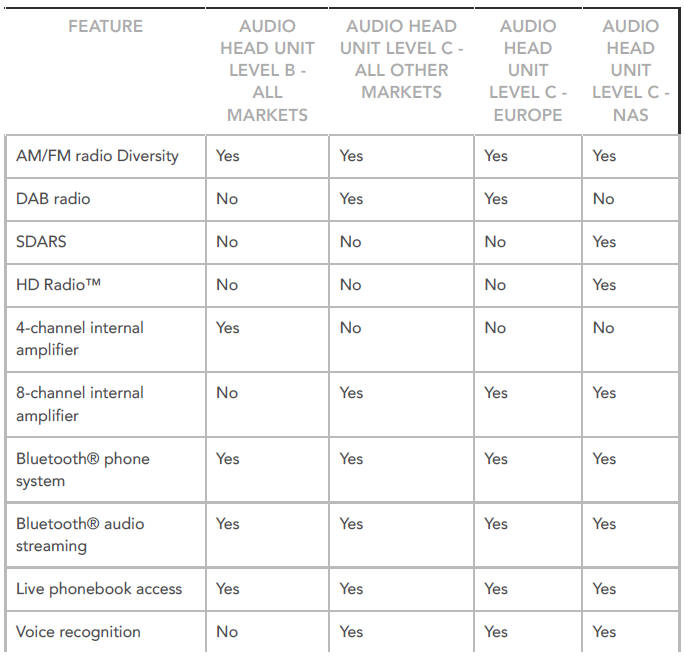
The AHU receives a 12V fused power supply from the Battery Junction Box (BJB) and the Quiescent Current Control Module (QCCM).
Medium speed Controller Area Network (CAN) Comfort system bus connections provide communication with other system control modules, for example; inputs from the Parking Aid Control Module (PACM) for sound generation and display on the TS.
The AHU uses APIX2 which is a new protocol for video output to the Touch Screen (TS). APIX2 is a high speed digital serial link capable of communicating up to 1 Gbit/second of digital video data. The serial link can support simultaneous video, audio and data transmission from the AHU and the TS.
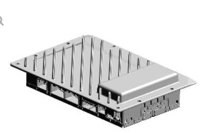
INTEGRATED AUDIO MODULE (IAM) - INCONTROL TOUCH PLUS AUDIO SYSTEMS
The Integrated Audio Module (IAM) is located in the center of the instrument panel, below the TS. The IAM communicates with the Bluetooth mobile phone via the Bluetooth phone module which has an integral Bluetooth antenna and software for mobile phone functionality.
The IAM has the following features:
- Navigation 40GB Hard Disc Drive (HDD) (30GB used for Navigation)
- TMC/(VICS Japan only)
- Off Road Navigation
- 40GB HDD (10GB used for music storage) - virtual CD/DVD - allows the storage of up to 10 CDs to create a 'virtual' multi-changer
- Voice recognition
- DVD output to Rear Seat Entertainment (RSE)
- Wireless headphones.
The IAM contains the following functionality:
- AM/FM radio tuner with diversity
- HD Radio receiver (NAS only)
- CD/MP3 player (Single CD)
- Auxiliary audio/video is available via a portable audio interface panel. The panel allows for the connection of portable audio/video via 2 USB's, a 3.5mm jack plug and iPod connectivity.
- Bluetooth and audio streaming.
When the vehicle systems become active, the TS is woken up by CAN bus activity and subsequently wakes up the IAM via the MOST.
The IAM incorporates an Amplitude Modulation (AM)/Frequency Modulation (FM) tuner which allows for the storage of 3 banks of FM presets, FM1/2/3, containing 6 presets each and 3 banks of AM Presets, AM1/AM2/AMA, containing 6 presets each. The AMA bank gives the 6 strongest AM stations stored by an AM autostore. Pre-set stations are stored in the IAM memory. The radio tuner also incorporates the following radio functions:
- HD Radio (NAS only)
- AM Auto Store (AST)
- FM station list
- Presets
- Traffic announcements (TA) - Europe only
- RDS (radio data system) / (Radio Broadcast Data System (RBDS) in NAS markets) functions:
- Station name
- Radio text
- PTY
- Traffic Announcements (TA) (Not NAS)
- AF switching (Not NAS)
- REG to lock to regional/local broadcast (Not NAS)
- Seek station
- Tune up/down.
When the optional Digital Radio Control Module (DRCM) is specified, the audio system is fitted with a separate digital radio tuner. This allows the reception of digital broadcast stations which can be received via the FM2/digital radio band III antenna located in the rear spoiler or via the digital radio band L antenna in the roof pod.
In NAS markets, Satellite Digital Audio Radio Service (SDARS) can be specified; the audio system is fitted with a separate Satellite Radio Control Module (SRCM). This allows for the reception of the satellite digital broadcast stations which are received via a satellite radio antenna located in the roof pod.
All radio antennas are routed into the IAM. The IAM supplies a power output to the AM/FM antenna amplifier.
The IAM incorporates a power management function. Should the vehicle battery level drop below a predetermined level, the unit will limit its functionality. The IAM receives MOST signals from the TS. The TS receives medium speed CAN bus signals from other vehicle systems which it uses to determine the wake up/shut down process for the modules on the MOST ring.
Calibration of the IAM using approved Land Rover diagnostic equipment enables updates to be downloaded as new technology becomes available or any fault concerns require software updates. If the IAM is replaced it must be configured as a new module using approved Land Rover diagnostic equipment.
CD PLAYER / DVD PLAYER
The CD player has the capability to play MP3 files. The MP3 discs follow a format of folders and files within the folder. It is also possible to place all the files in the root directory on the virtual CD.
The random and repeat features follow the normal CD random and repeat feature functions.
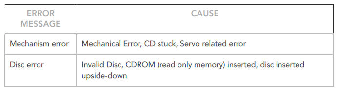
When a CD error occurs, the IAM will alert the user by showing a message related to the error in the TS. This will be displayed while the CD audio mode is selected until the error is corrected. The CD related error does not affect other areas of the IAM and a different audio source can be selected.
The IAM has the ability to load audio files and 'rip' the music onto the internal hard drive, a 10GB partition is reserved to store music. It is possible to store up to 10 uncompressed albums onto the hard drive. Only CDDA files can be loaded into the virtual changer.
File compatibility for the single slot CD mechanism includes:
- CD audio
- MP3 - (MPEG Layer III)
- WMA - (Microsoft Windows Media Audio)
- WAV - (waveform)
- AAC - (Advanced Audio Coding. Apple iTunes - only through iPod interface).
NOTE:
The CD player may take a longer time to load an MP3 disc, if there are more tracks than on a normal CD. To minimise loading time, a rigid folder structure is recommended.
In the event of customer complaints relating to audio quality, file compression should be taken into consideration during diagnosis.
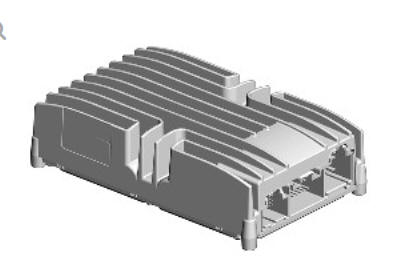
AUDIO AMPLIFIER MODULE (AAM)
Systems with an external Audio Amplifier Module (AAM) have the AAM located below the front left seat. The AAM is a secured with a bracket to the vehicle floorpan.
The audio systems have four AAM options, dependent on level of audio system fitted:
- 6 channel 190W AMM used on the InControl Touch - 10 speaker system
- 8 channel 250W AAM used on the InControl Touch - 11 speaker system
- 8 channel 250W AAM used on the InControl Touch Plus - 11 speaker system
- 15 channel 825W AAM used on the InControl Touch Plus with Meridian Surround - 17 speaker system.
InControl Touch 10 and 11 Speaker Systems
The InControl Touch 10 and 11 speaker systems both use an AAM specific to the system. The AAMs are similar in design, with the only difference being the power outputs; 190W or 250W.
The AAM has three connectors which provide for power and ground connections, CAN infotainment systems bus between the AHU and the AAM and hardwired connections to the vehicle speakers.
The AAM processes signals from other system modules for output via the vehicle speakers.
Power supplies are received from the Rear Junction Box (RJB).
InControl Touch Plus Audio System
The 250W AAM is connected to the other audio system components on the MOST ring. The AAM processes incoming audio signals from other system modules on the MOST ring. Hardwired connectors provide outputs for the vehicle speakers, output to the headphone transmitter and power and ground. Power supplies are received from the RJB and the Quiescent Current Control Module (QCCM).
InControl Touch Plus with Meridian Surround System
The 825W AAM is connected to the other audio system components on the MOST ring. The AAM processes incoming audio signals from other system modules on the MOST ring. Hardwired connectors provide outputs for the vehicle speakers, output to the headphone transmitter and power and ground. Power supplies are received from the RJB and the Quiescent Current Control module (QCCM).
LEFT STEERING WHEEL SWITCHPACK
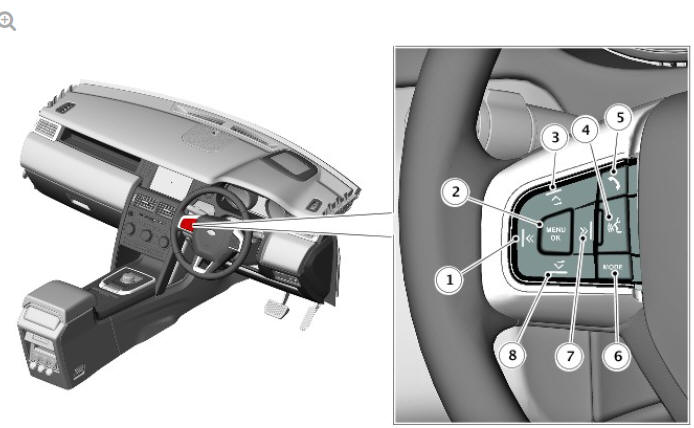
- Seek, previous radio preset, previous track, scroll down telephone list switch
- Menu/OK switch (instrument cluster menu control)
- Volume increase switch
- Voice control switch
- Telephone answer/end call switch
- Mode switch
- Seek, next radio preset, next track, scroll up telephone list switch
- Volume decrease switch
The left steering wheel switchpack is located on the left side of the steering wheel.
On the InControl Touch systems, the switches are a resistive ladder type which apply a different voltage via a Local Interconnect Network (LIN) bus to the Audio Head Unit (AHU) in response to different switches being pressed.
On the InControl Touch Plus audio system and the InControl Touch Plus with Meridian Surround system, the switches are resistive ladder type which apply a different voltage to the via a LIN bus to the Touch Screen (TS) in response to different switches being pressed.
The left steering wheel switchpack controls the following switch functions:
- MODE - Press repeatedly to scroll through all audio/video sources
- " Short press up:
- to select the next radio preset
- to select the next track on chosen audio source
- when telephone is in use, press to scroll up lists of calls or phonebook entries.
- " Short press down:
- to select the previous radio preset
- to select the previous track or start of current track on chosen audio source
- when telephone is in use, press to scroll down lists of calls or phonebook entries.
- With radio manual seek mode activated, further short presses will change the frequency in single increments. A further long press will scan forwards through the current waveband until the switch is released
- " Long press up:
- to auto seek up the frequency to the next radio station.
- " Long press down:
- to auto seek down the frequency to the next radio station.
- Volume increase for any audio source
- Volume decrease for any audio source.
The MENU/OK switch is for use with the instrument cluster menu. For additional information refer to Instrument cluster.
For further details on the telephone switch refer to Cellular Phone. For additional information refer to Cellular Phone.
For further details on the voice switch refer to Voice Control. For additional information refer to Voice Control.
READ NEXT:
 Portable Audio Interface Panel
For InControl Touch systems with Navigation, voice control or telephone
For InControl Touch Plus audio system and InControl Touch Plus with
Meridian
surround system
For InControl Touch audio
Satellite Radio Control Module (SRCM) - Nas only
The Satellite Radio Control Module (SRCM) is located below the front right
seat. The SRCM is secured to a mounting brackets and secured with flanged
nuts.
The SCRM is a dedicated tuner which is con
Audio System / Operation
MEDIA ORIENTED SYSTEMS TRANSPORT (MOST) - INCONTROL
TOUCH PLUS AUDIO SYSTEM AND INCONTROL TOUCH PLUS WITH
MERIDIAN SURROUND AUDIO SYSTEM ONLY
The components of the audio/infotainment systems are conne
SEE MORE:
Rear Drive Axle - Differential - Vehicles with - Active Driveline Differential
Control Module (G1781294) / Removal and Installation
REMOVAL
NOTES:
This procedure contains some variation in the illustrations
depending on the vehicle specification, but the essential
information is always correct.
This procedure contains illustrations showing certain components
removed to provide extra clarity.
Raise and support the vehicle
Airbag service information
Phone systems should only be
installed by qualified persons
familiar with the operation of, and
requirements for, vehicles fitted
with a Supplementary Restraint
System (SRS). If you are in any
doubt, seek advice from your
Retailer/Authorised Repairer.
Do not attempt to service, repair,
re
