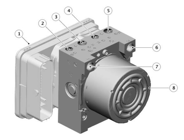
Land Rover Discovery: Hydraulic Control Unit (HCU)

- Anti-lock Brake System (ABS) control module
- Secondary circuit port
- Left front caliper port
- Right front caliper port
- Primary circuit port
- Left rear caliper port
- Right rear caliper port
- Hydraulic Control Unit (HCU)
The Hydraulic Control Unit (HCU) is located on the rear left side of the engine compartment and is an integral component with the Anti-lock Brake System (ABS) control module. The HCU is a four channel unit that modulates the supply of hydraulic pressure to the brakes under the control of the ABS control module.
The primary and secondary outlet ports of the master cylinder are connected via 8mm (0.315in) diameter brake pipes to the primary and secondary circuits of the HCU. The primary circuit in the HCU provides two separate outlet ports to the right front and left rear brakes. The secondary circuit in the HCU provides two separate outlet ports to the left front and right rear brakes.
The HCU incorporates three brake operating modes as follows:
- Normal braking/Electronic Brake Force Distribution (EBD).
- ABS braking.
- Active braking.
As the HCU and ABS module is a fully integrated unit, details of the HCU and ABS functionality, including the three braking modes, are contained in the Anti-Lock Control - Traction Control section of the manual.
For additional information, refer to: Anti-Lock Control - Traction Control (206-09B, Description and Operation).
SERVICING INFORMATION
The Hydraulic Control Unit (HCU) and Anti-lock Brake System (ABS) control module form a single component and must not be separated. The HCU and ABS control module assembly is supplied in a pre-filled state. After installation, the hydraulic brake system only requires a conventional bleed of the system; there is no requirement to pressure bleed the system.
OPERATION
As the brake pedal is pressed, the front push rod in the brake booster pushes the master cylinder primary piston along the bore of the housing.
This produces pressure in the primary pressure chamber and in conjunction with the primary spring, overcomes the secondary spring and simultaneously moves the secondary piston along the bore.
The initial movement of the pistons away from the piston stops closes the primary and secondary center valves located inside the master cylinder.
Further movement of the pistons then pressurizes the fluid in the primary and secondary chambers and the brake circuits. The fluid in the chambers behind the pistons is unaffected by the movement of the pistons and will flow unrestricted through the inlet ports, between the chambers and the reservoir.
Pressurized fluid enters the Hydraulic Control Unit (HCU). The HCU then modulates the supply of pressurized fluid to the brakes under control of the Anti-lock Brake System (ABS) control module.
For additional information, refer to: Anti-Lock Control - Traction Control (206-09B, Description and Operation).
Hydraulic brake actuation specifications
Torque Specifications
.jpg)

