Land Rover Discovery: Keyless Vehicle Module (G2006704) / Removal and Installation
Land Rover Discovery (2009–2016) Service Manual / Electrical / Electronic Feature Group / Keyless Vehicle Module (G2006704) / Removal and Installation
REMOVAL
- Disconnect the battery ground cable.
Refer to: Specifications (414-01 Battery, Mounting and Cables, Specifications).
- Remove the loadspace trim panel.
Refer to: Loadspace Trim Panel (501-05 Interior Trim and Ornamentation, Removal and Installation).
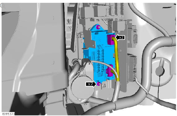
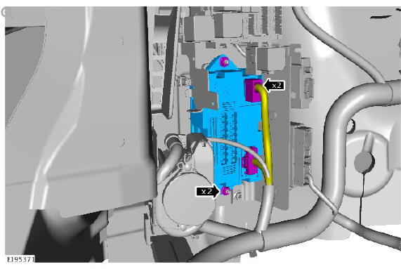
- 1. Remove the wiring harness.
- 2. Remove the 2 nuts.
- 3. Remove the Quiescent Current Control Module
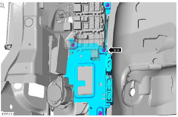
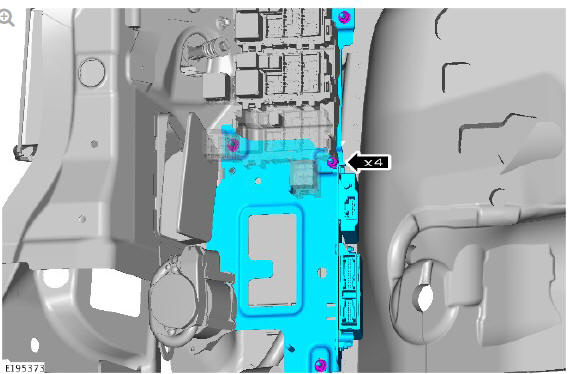
- Remove the 4 nuts.
CAUTION:
Take extra care not to damage the wiring harnesses.
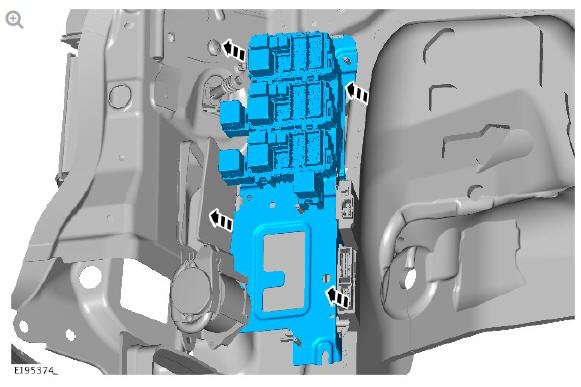
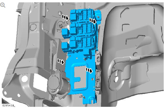
- Remove the rear junction box.

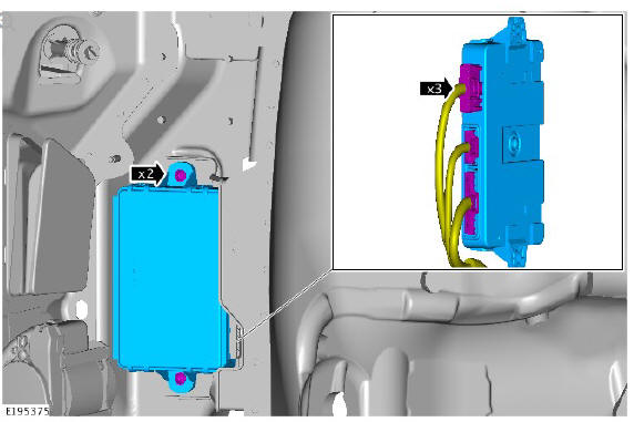
- 1. Remove the 2 bolts.
- 2. Remove the Keyless Vehicle Module.
- 3. Remove the wiring harness.
INSTALLATION
- 1. Install the wiring harness.
- 2. Install the Keyless Vehicle Module.
- 3. Install the 2 bolts.
Torque: 9 Nm
- Install the Rear Junction Box.
- Install the 2 nuts.
Torque: 9 Nm
- 1. Install the Quiescent Current Control Module.
- 2. Install the 2 nuts.
Torque: 9 Nm
- 3. Install the wiring harness.
- Install the loadspace trim panel.
Refer to: Loadspace Trim Panel (501-05 Interior Trim and Ornamentation, Removal and Installation).
- Connect the battery ground cable.
Refer to: Specifications (414-01 Battery, Mounting and Cables, Specifications).
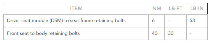
Multifunction electronic modules specifications
Torque Specifications
READ NEXT:
 Navigation System / Diagnosis and Testing
PRINCIPLES OF OPERATION
For a detailed description of the Navigation System, refer to the relevant
Description and Operation section in the workshop manual. REFER to:
Navigation System (415-01 Informa
Passenger Door Module / Diagnosis and Testing
PRINCIPLES OF OPERATION
For a detailed description of the Passenger Door Module, refer to the
relevant Description and Operation section in the workshop manual. REFER
to: Handles, Locks, Latches and E
SEE MORE:
Automatic Transmission Transaxle
/ Description and operation
COMPONENT LOCATION
Paddle switches - upshift / downshift
Transmission Control Switch (TCS)
Transmission Control Module (TCM)
ZF 9HP48 Automatic transmission
Automatic Transmission Fluid (ATF) cooler with integrated thermostat
OVERVIEW
The ZF 9HP48 automatic transmission is a 9 speed, electr
Sectioned View of Typical
Fuel Fired
Booster Heater
Combustion air fan
Coolant inlet
Coolant outlet
Burner insert
Heat exchanger
Overheat temperature sensor
Exhaust
Fuel inlet
Evaporator
Air inlet
COMBUSTION AIR FAN
The combustion air fan regulates the flow of air into the FFBH to support
combustion of the fuel supplied by the FFBH fuel
© 2019-2026 Copyright www.lrdisc.com
