Land Rover Discovery: Navigation System / Diagnosis and Testing
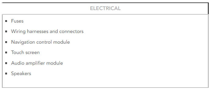
PRINCIPLES OF OPERATION
For a detailed description of the Navigation System, refer to the relevant Description and Operation section in the workshop manual. REFER to: Navigation System (415-01 Information and Entertainment System, Description and Operation).
INSPECTION AND VERIFICATION
CAUTION:
Diagnosis by substitution from a donor vehicle is NOT acceptable.
Substitution of control modules does not guarantee confirmation of a fault, and may also cause additional faults in the vehicle being tested and/or the donor vehicle.
NOTES:
- If a control module or a component is suspect and the vehicle remains under manufacturer warranty, refer to the Warranty Policy and Procedures manual, or determine if any prior approval programme is in operation, prior to the installation of a new module/component.
- When performing voltage or resistance tests, always use a digital multimeter accurate to three decimal places, and with an up-todate calibration certificate. When testing resistance always take the resistance of the digital multimeter leads into account.
- Check and rectify basic faults before beginning diagnostic routines involving pinpoint tests.
- Verify the customer concern
- Visually inspect for obvious signs of damage and system integrity If an obvious cause for an observed or reported concern is found, correct the cause (if possible) before proceeding to the next step
Visual Inspection
- If an obvious cause for an observed or reported concern is found, correct the cause (if possible) before proceeding to the next step
- If the cause is not visually evident, verify the symptom and refer to the Symptom Chart, alternatively check for Diagnostic Trouble Codes (DTCs) and refer to the DTC Index
- Check DDW for open campaigns. Refer to the corresponding bulletins and SSMs which may be valid for the specific customer complaint and carry out the recommendations as required
SYMPTOM CHART
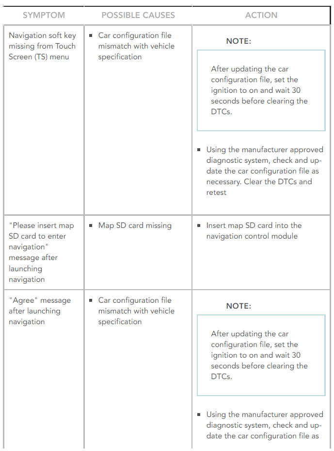
SYMPTOM:
Navigation soft key missing from Touch Screen (TS) menu
POSSIBLE CAUSES:
- Car configuration file mismatch with vehicle specification
ACTION:
NOTE:
After updating the car configuration file, set the ignition to on and wait 30 seconds before clearing the DTCs.
- Using the manufacturer approved diagnostic system, check and update the car configuration file as necessary. Clear the DTCs and retest
SYMPTOM:
"Please insert map SD card to enter navigation" message after launching navigation
POSSIBLE CAUSES:
- Map SD card missing
ACTION:
- Insert map SD card into the navigation control module
SYMPTOM:
"Agree" message after launching navigation
POSSIBLE CAUSES:
- Car configuration file mismatch with vehicle specification
ACTION:
NOTE:
After updating the car configuration file, set the ignition to on and wait 30 seconds before clearing the DTCs.
- Using the manufacturer approved diagnostic system, check and update the car configuration file as necessary. Clear the DTCs and retest
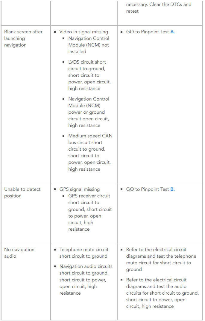
SYMPTOM:
Blank screen after launching navigation
POSSIBLE CAUSES:
Video in signal missing
- Navigation Control Module (NCM) not installed
- LVDS circuit short circuit to ground, short circuit to power, open circuit, high resistance
- Navigation Control Module (NCM) power or ground circuit open circuit, high resistance
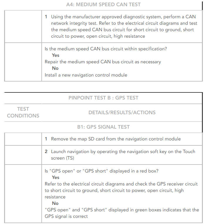
- Medium speed CAN bus circuit short circuit to ground, short circuit to power, open circuit, high resistance
ACTION:
- GO to Pinpoint Test A.
SYMPTOM:
Unable to detect position
POSSIBLE CAUSES:
GPS signal missing
- GPS receiver circuit short circuit to ground, short circuit to power, open circuit, high resistance
ACTION:
- GO to Pinpoint Test B.
SYMPTOM:
No navigation audio
POSSIBLE CAUSES:
- Telephone mute circuit short circuit to ground
- Navigation audio circuits short circuit to ground, short circuit to power, open circuit, high resistance
ACTION:
- Refer to the electrical circuit diagrams and test the telephone mute circuit for short circuit to ground
- Refer to the electrical circuit diagrams and test the audio circuits for short circuit to ground, short circuit to power, open circuit, high resistance
PINPOINT TESTS
NOTES:
- The navigation control module is installed at the factory for China, Hong Kong, Taiwan and Macau market vehicles.
- The navigation control module is not installed at the factory for Korea, India and Israel market vehicles.
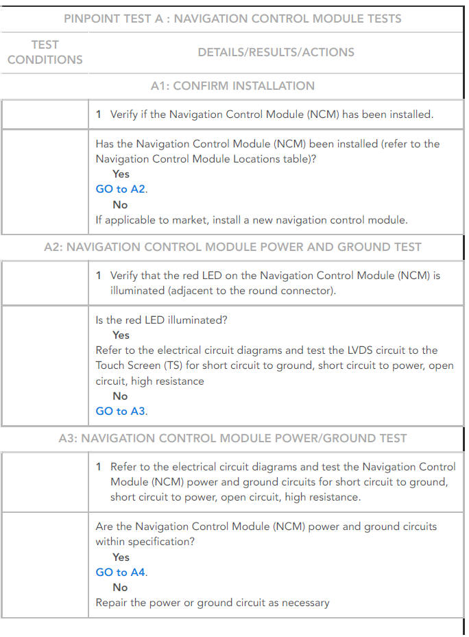
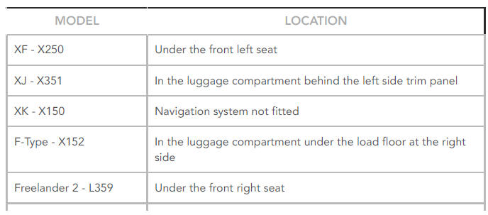
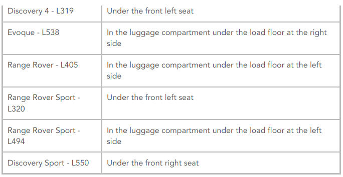
NAVIGATION CONTROL MODULE INSTALLED LOCATIONS
DTC INDEX
For a list of Diagnostic Trouble Codes (DTCs) that could be logged on this vehicle, please refer to Section 100-00. REFER to: (100-00 General Information)
Diagnostic Trouble Code Index - DTC: Navigation Control Module (NCM) - Extended Markets (Description and Operation), Diagnostic Trouble Code Index - DTC: Navigation Control Module (NCM) - Japan (Description and Operation).
READ NEXT:
 Passenger Door Module / Diagnosis and Testing
PRINCIPLES OF OPERATION
For a detailed description of the Passenger Door Module, refer to the
relevant Description and Operation section in the workshop manual. REFER
to: Handles, Locks, Latches and E
Antenna
COMPONENT LOCATION
Radio Frequency (RF) filter
Amplitude Modulation (AM)/Frequency Modulation (FM) antenna amplifier
Television (TV) antenna amplifier
TV antenna amplifier
Global Positioning Sy
SEE MORE:
Manual Transmission Transaxle
Transmission Fluid
Level Check (G2162887)
/ General Procedures
CHECK
WARNING:
Observe due care when draining, as the fluid can be very hot.
All vehicles
WARNING:
Make sure to support the vehicle with axle stands.
NOTE:
Make sure that the vehicle is standing on a level surface.
Raise and support the vehicle.
Refer to: Engine Undershield (501-02 Front End Body Pa
Headlamp Leveling
PRINCIPLES OF OPERATION
For a detailed description of the Headlamp Leveling system, refer to the
relevant Description and Operation section in the workshop manual. REFER
to: Exterior Lighting (417-01 Exterior Lighting, Description and Operation).
INSPECTION AND VERIFICATION
CAUTION:
Diagnosis by sub
