Land Rover Discovery: Transmission Transaxle Cooling Description and Operation
COMPONENT LOCATION - ZF 9HP48 TRANSMISSION TD4 2.2L DIESEL
- Automatic Transmission Fluid (ATF) cooler
COMPONENT LOCATION - ZF 9HP48 TRANSMISSION GTDi 2.0L PETROL
- Automatic Transmission Fluid (ATF) cooler
OVERVIEW
The ZF 9HP48 automatic transmission uses an external ATF (automatic transmission fluid) cooler to reduce the temperature of the transmission fluid.
A plate type cooler uses engine coolant to reduce the ATF temperature.
DESCRIPTION
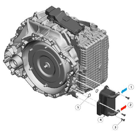
- Engine coolant inlet
- Engine coolant outlet
- Torx screw (3 off)
- ATF Cooler
- Seals
The ATF cooler is located on the transmission main casing. The ATF cooler is an aluminium housing comprising louvred fins and plates. The plates allow a cross-flow of ATF and engine coolant through the ATF cooler. The plates are immersed in the engine coolant from the 'cold' side of the radiator which provides cooling of the ATF by the temperature differential between the ATF and the engine coolant.
The engine cooling system has a low temperature zone in the top third of the radiator. The engine coolant flow through this section of the radiator is restricted by the ATF cooler. Therefore the engine coolant has a slower flow rate across the cooling tubes of this section of the radiator. This cools the engine coolant more than the lower part of the radiator and consequently provides increased cooling of the ATF.
The ATF cooler has an integral thermostatic valve, which controls the ATF flow through the cooler. Flow is restricted to improve ATF warm-up time.
The thermostatic valve is closed at temperatures of 78ºC (172ºF) and below, starts to open at temperatures of between 78 and 84ºC (172 and 183ºF) and is fully open at temperatures of 96ºC (204ºF) and higher.
OPERATION
AUTOMATIC TRANSMISSION FLUID (ATF) COOLER
Engine coolant is circulated through the ATF cooler which cools the ATF flowing through the ATF cooler by the temperature differential between the two fluids.
Transmission transaxle cooling diagnosis and testing
PRINCIPLES OF OPERATION
For a detailed description of the Automatic Transmission Cooling system, refer to the relevant Description and Operation section in the workshop manual. REFER to: Transmission Cooling (307-02 Transmission/Transaxle Cooling, Description and Operation).
INSPECTION AND VERIFICATION
CAUTION:
Diagnosis by substitution from a donor vehicle is NOT acceptable.
Substitution of control modules does not guarantee confirmation of a fault, and may also cause additional faults in the vehicle being tested and/or the donor vehicle.
NOTES:
- If a control module or a component is suspect and the vehicle remains under manufacturer warranty, refer to the Warranty Policy and Procedures manual, or determine if any prior approval programme is in operation, prior to the installation of a new module/component.
- When performing voltage or resistance tests, always use a digital multimeter accurate to three decimal places, and with an up-todate calibration certificate. When testing resistance always take the resistance of the digital multimeter leads into account.
- Check and rectify basic faults before beginning diagnostic routines involving pinpoint tests.
- Verify the customer concern
- Visually inspect for obvious signs of damage and system integrity
Visual Inspection
- If an obvious cause for an observed or reported concern is found, correct the cause (if possible) before proceeding to the next step
- If the cause is not visually evident, verify the symptom and refer to the Symptom Chart, alternatively check for Diagnostic Trouble Codes (DTCs) and refer to the DTC Index
- Check DDW for open campaigns. Refer to the corresponding bulletins and SSMs which may be valid for the specific customer complaint and carry out the recommendations as required
SYMPTOM CHART
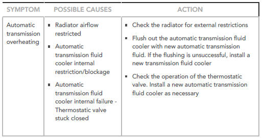
SYMPTOM:
Automatic transmission overheating
POSSIBLE CAUSES:
- Radiator airflow restricted
- Automatic transmission fluid cooler internal restriction/blockage
- Automatic transmission fluid cooler internal failure - Thermostatic valve stuck closed
ACTION:
- Check the radiator for external restrictions
- Flush out the automatic transmission fluid cooler with new automatic transmission fluid. If the flushing is unsuccessful, install a new transmission fluid cooler
- Check the operation of the thermostatic valve. Install a new automatic transmission fluid cooler as necessary
DTC INDEX
For a list of Diagnostic Trouble Codes (DTCs) that could be logged on this vehicle, please refer to Section 100-00. REFER to: Diagnostic Trouble Code Index - DTC: Transmission Control Module (TCM) (100-00 General Information, Description and Operation).
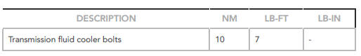
Transmission transaxle cooling specifications
Torque Specifications
READ NEXT:
 Accessory Drive - Ingenium
i4 2.0l Diesel Accessory
Drive Belt (G1882049)
/ Removal and Installation
Accessory Drive - Ingenium
i4 2.0l Diesel Accessory
Drive Belt (G1882049)
/ Removal and Installation
REMOVAL
NOTES:
Removal steps in this procedure may contain installation details.
Engine shown removed for clarity.
Disconnect the battery ground cable.
Refer to: Specifications (414-01 Battery, M
SEE MORE:
Power Steering Steering
Gear (G1778594) / Removal and
Installation
PART(S)
REMOVAL
CAUTION:
The suspension arm nuts and bolts must be tightened with the
suspension arms in the normal ride position. Failure to follow this
instruction may result in premature failure of the bushing.
NOTES:
Only use clean water as a lubricant for the bushing, if required
This proce
Hydraulic Jack
WARNINGS:
Before commencing work on underside of vehicle, ensure that
axle
stands are correctly positioned and vehicle is securely supported.
Always chock the rear wheels when jacking the front of the
vehicle.
A hydraulic jack with a minimum lifting capacity of 1500 kg, (3,300 lbs) must
be
