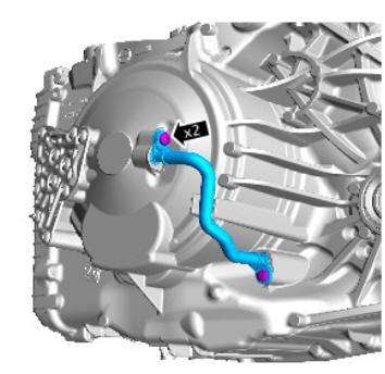
Land Rover Discovery: Transmission Oil Supply Pipe (G1707722) / Removal and Installation
REMOVAL
WARNING:
Be prepared to collect escaping fluids.
NOTES:
- Some variation in the illustrations may occur, but the essential information is always correct.
- Removal steps in this procedure may contain installation details.
- Refer to: Wheel and Tire (204-04, Removal and Installation).
CAUTION:
Make sure that the mating faces are clean and free of foreign material.
INSTALLATION
- To install, reverse the removal procedure.
- Carry out a transmission fluid level check.
Refer to: Transmission Fluid Level Check (307-01, General Procedures).
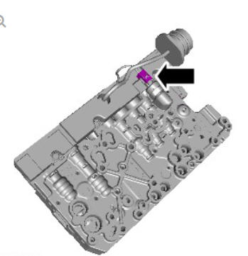
Transmission pressure sensor (G1948803) removal and installation
REMOVAL
WARNING:
Be prepared to collect escaping fluids.
CAUTIONS:
- Extreme cleanliness must be exercised when handling this component.
- Make sure that the area around the component is clean and free of foreign material.
NOTES:
- Some variation in the illustrations may occur, but the essential information is always correct.
- Removal steps in this procedure may contain installation details.
Remove the main control valve body.
Refer to: Main Control Valve Body - INGENIUM I4 2.0L Diesel (307- 01 Automatic Transmission/Transaxle, Removal and Installation).
Refer to: Main Control Valve Body - TD4 2.2L Diesel (307-01 Automatic Transmission/Transaxle, Removal and Installation).
Refer to: Main Control Valve Body - GTDi 2.0L Petrol/GTDi 2.0L Petrol - SULEV (307-01 Automatic Transmission/Transaxle, Removal and Installation).
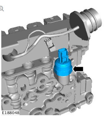
Torque: 12 Nm
INSTALLATION
- To install, reverse the removal procedure.
READ NEXT:
 Transmission Transaxle Cooling
Description and Operation
Transmission Transaxle Cooling
Description and Operation
COMPONENT LOCATION - ZF 9HP48 TRANSMISSION TD4 2.2L DIESEL
Automatic Transmission Fluid (ATF) cooler
COMPONENT LOCATION - ZF 9HP48 TRANSMISSION GTDi 2.0L PETROL
Automatic Transmission Fluid (
SEE MORE:
Legal Compliance
Some sites may have a discharge consent for effluent discharge to the foul
drain for a car wash etc. It is essential to know the types of effluent which
are allowed to be discharged into the drain and to check the results of any
monitoring carried out by the Water Company.
Where paint spraying oper
Variable Сamshaft Еiming (VCT) - Exhaust Camshaft Only
Exhaust VCT solenoid
Exhaust VCT actuator
The timing of the exhaust camshaft can be adjusted independently by an oil
pressure controlled torsional assist VCT system. The VCT solenoid which is
controlled electrically determines the position of the VCT actuator which has
a direct interface with
