Land Rover Discovery: Satellite Radio Tuner (G1785144) / Removal and installation
Land Rover Discovery (2009–2016) Service Manual / Electrical / Information and Entertainment System / Satellite Radio Tuner (G1785144) / Removal and installation
REMOVAL
NOTE:
Removal steps in this procedure may contain installation details.
Disconnect the battery ground cable.
Refer to: Specifications (414-01 Battery, Mounting and Cables, Specifications).
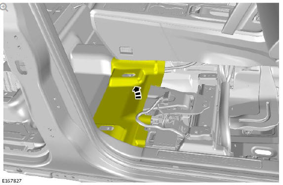
Remove the right front seat Refer to: Front Row Seat - Vehicles With: Power Seats (501-10 Seating, Removal and Installation).
.jpg)
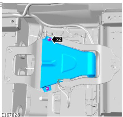
Torque: 9 Nm
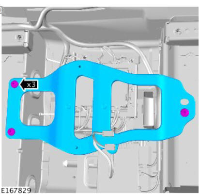
Torque: 6 Nm
INSTALLATION
- To install, reverse the removal procedure.
READ NEXT:
 Diagnosis and Testing Speakers
PRINCIPLES OF OPERATION
For a detailed description and operation of the information and
entertainment system, refer to the relevant description and operation
section of the workshop manual.
INSPECTION
Diagnosis and Testing Telematics
The complexities of the electronics involved with the telematics system, of
which the GPS antenna and navigation display are parts, and the
multiplexed communication network which are connected to it
Front Door Speaker (G1785139) / Removal and Installation
REMOVAL
NOTES:
Removal steps in this procedure may contain installation details.
RH illustration shown, LH is similar.
Refer to: Front Door Trim Panel (501-05 Interior Trim and
Ornamentation, Remo
SEE MORE:
Gradient release control (GRC)
With Hill Descent Control (HDC) activated,
if the vehicle is stopped on a slope using
the brake pedal, GRC will become active
(except in the Terrain response system's
Sand program). During a hill ascent, when
the brake pedal is released, GRC will
automatically delay and graduate the
brake release, t
Manual seats / Electric seats
Manual seats
Forward and rearward adjustment.
Height adjustment.
Seatback angle adjustment.
For information on how to adjust the front
head restraint
Do not adjust the seat while the
vehicle is moving; doing so could
cause a loss of vehicle control and
personal injury.
Electric seats
Lumb
© 2019-2026 Copyright www.lrdisc.com
