Land Rover Discovery: Speakers / Description / Operation
Description
INCONTROL TOUCH 6 SPEAKER SYSTEM
The system comprises 6 speakers:
- 2 tweeters, aluminium dome, 25mm, 4 Ohm, 50W maximum
- 4 bass, paper cone, rubber edge, 165mm, 2 Ohm, 100W maximum.
INCONTROL TOUCH 10 SPEAKER SYSTEM
The system comprises 10 speakers:
- 4 tweeters, aluminium dome, 25mm, 4 Ohm, 50W maximum
- 4 bass, paper cone, rubber edge, 165mm, 2 Ohm, 100W maximum
- 2 mid-range, Glass Fibre, Poly Resin cone, rubber edge, 2 Ohm, 100W maximum
INCONTROL TOUCH 11 SPEAKER SYSTEM
The system comprises 11 speakers:
- 4 tweeters, aluminium dome, 25mm, 4 Ohm, 50W maximum
- 4 bass, paper cone, rubber edge, 165mm, 2 Ohm, 100W maximum
- 2 mid-range, Glass Fibre, Poly Resin cone, rubber edge, 2 Ohm, 100W maximum
- Sub-woofer, paper cone, rubber edge, 250mm, 2 x 2 Ohm, 2 x 100W max
INCONTROL TOUCH PLUS SYSTEM
The system comprises 11 speakers:
- 4 tweeters, aluminium dome, 25mm, 4 Ohm, 50W maximum
- 4 bass, paper cone, rubber edge, 165mm, 2 Ohm, 100W maximum
- 2 mid-range, Glass Fibre, Poly Resin cone, rubber edge, 2 Ohm, 100W maximum
- Sub-woofer, paper cone, rubber edge, 250mm, 2 x 2 Ohm, 2 x 100W max
INCONTROL TOUCH PLUS WITH MERIDIAN SURROUND SYSTEM
The system comprises 17 speakers:
- 4 tweeters, aluminium dome, 25mm, 4 Ohm, 50W maximum
- 4 bass, paper cone, rubber edge, 165mm, 2 Ohm, 100W maximum
- 2 mid-range, Glass Fibre, Poly Resin cone, rubber edge, 2 Ohm, 100W maximum
- 3 co-axial (contains 1 tweeter and 1 mid-range per speaker), tweeter aluminum cone, mid-range Poly Resin cone, rubber edge, 2 Ohm, 100W maximum
- Sub-woofer, paper cone, rubber edge, 250mm, 2 x 2 Ohm, 2 x 100W max
SUB-WOOFER
The dual voice coil sub-woofer speaker is located in the rear right side of the luggage compartment. A single 4 pin connector, connects the subwoofer to the vehicle wiring harness. The low-frequency bass sound from the sub-woofer complements the higher frequency sounds from the other system speakers.
The sub-woofer is powered by the AAM.
Operation
INCONTROL TOUCH 6 SPEAKER SYSTEM
The InControl System uses an Audio Head Unit (AHU) which contains an integral audio amplifier. The speakers are connected directly to the AHU for this system.
Audio signal originate from the AHU and are passed to the vehicle speakers via hardwired connections. Audio signals can also be generated by other vehicle systems which are passed to the AHU on the Medium speed Controller Area Network (CAN) comfort systems bus. The AHU processes the signals and passes the audio output to the speakers.
The AHU receives a fused power supply from the Battery Junction Box (BJB), via the Quiescent Current Control Module (QCCM).
INCONTROL TOUCH 10 AND 11 SPEAKER SYSTEMS
The InControl Touch 10 speaker and InControl Touch 11 speaker systems use an external Audio Amplifier Module (AAM). The speakers for these systems are connected directly to the AAM.
Audio signals originate from the AHU and are passed to the AAM via a medium speed CAN infotainment bus system. The speakers are connected directly to the AAM.
Audio signals can also be generated by other vehicle systems. The AHU processes the signals and passes the output to the AAM via the medium speed CAN infotainment systems bus and hardwired connections.
The AHU receives a fused power supply from the BJB, via the QCCM. The AAM receives a permanent fused power supply from the Rear Junction Box (RJB).
INCONTROL TOUCH PLUS SYSTEM AND INCONTROL TOUCH PLUS WITH MERIDIAN SURROUND SYSTEMS
The InControl Touch Plus System and the InControl Touch Plus with Meridian Surround Systems use an external Audio Amplifier Module (AAM). The speakers for these systems are connected directly to the AAM.
Audio signals originate from the IAM and are passed to the AAM on the Media Oriented System Transport (MOST) ring. Audio signals processed by other infotainment systems are passed to the AAM on the MOST.
Audio signals from systems not on the MOST ring, are passed to the AAM via the Gateway Module (GWM) on the medium speed CAN comfort systems bus to the Touch screen (TS). The TS then processes the signals and passes them to the AAM on the MOST ring.
The Integrated Audio Module (IAM) receives a fused power supply from the BJB via the QCCM. The AAM receives a permanent fused power supply from the BJB and RJB and a second power supply from the QCCM.
Speakers / Control diagram
CONTROL DIAGRAM - INCONTROL TOUCH 6 SPEAKER SYSTEM
NOTE:
A = Hardwired; AP = Medium speed CAN comfort systems bus
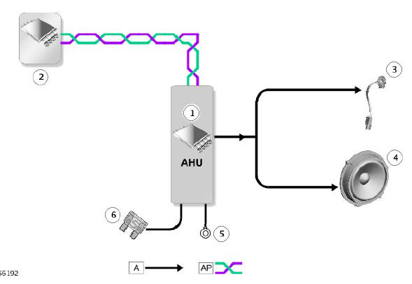
- Audio Head Unit (AHU)
- Audio inputs from other vehicle systems
- Tweeter speaker (2 off)
- Bass speaker (4 off)
- Ground
- Fused power supply from Battery Junction Box (BJB) and Quiescent Current Control Module (QCCM)
CONTROL DIAGRAM - INCONTROL TOUCH 10 SPEAKER SYSTEM
NOTE:
A = Hardwired; AP = Medium speed CAN comfort systems bus
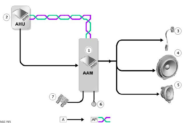
- Audio Amplifier Module (AAM)
- Audio Head Unit (AHU)
- Tweeter speaker (4 off)
- Bass speaker (4 off)
- Mid-range speaker (2 off)
- Ground
- Fused power supply from Battery Junction Box (BJB) and Quiescent Current Control Module (QCCM
CONTROL DIAGRAM - INCONTROL TOUCH 11 SPEAKER SYSTEM
NOTE:
A = Hardwired; AP = Medium speed CAN comfort systems bus
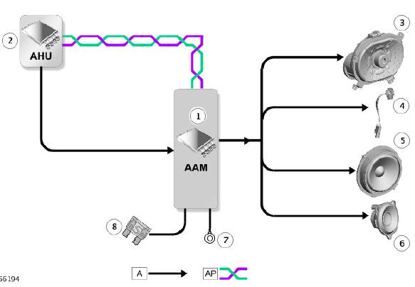
- Audio Amplifier Module (AAM)
- Audio Head Unit (AHU)
- Sub-woofer speaker
- Tweeter speaker (4 off)
- Bass speaker (4 off)
- Mid-range speaker (2 off)
- Ground
- Fused power supply from Battery Junction Box (BJB) and Quiescent Current Control Module (QCCM)
CONTROL DIAGRAM - INCONTROL TOUCH PLUS AND INCONTROL TOUCH PLUS WITH MERIDIAN SURROUND SYSTEMS
NOTE:
A = Hardwired; P = MOST bus
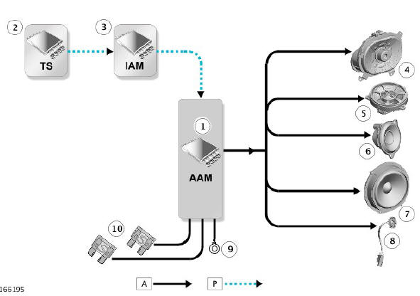
- Audio Amplifier Module (AAM)
- Touch Screen (TS)
- Integrated Audio Module (IAM)
- Sub-woofer speaker
- Co-axial speaker (3 off Meridian Surround system only)
- Mid-range speaker (2 off)
- Bass speaker (4 off)
- Tweeter speaker (4 off)
- Ground
- Fused power supply via the BJB and the RJB and a second power supply from the QCCM.
READ NEXT:
 Rear Door Speaker (G1785140) / Removal and Installation
REMOVAL
NOTES:
Removal steps in this procedure may contain
installation details.
LH illustration shown, RH is similar.
Refer to: Rear Door Trim Panel (501-05 Interior Trim and
Ornamentation, Rem
Satellite Radio Tuner (G1785144) / Removal and installation
REMOVAL
NOTE:
Removal steps in this procedure may contain installation
details.
Disconnect the battery ground cable.
Refer to: Specifications (414-01 Battery, Mounting and Cables,
Specifications).
R
Diagnosis and Testing Speakers
PRINCIPLES OF OPERATION
For a detailed description and operation of the information and
entertainment system, refer to the relevant description and operation
section of the workshop manual.
INSPECTION
SEE MORE:
Rear Suspension Rear
Stabilizer Bar
Bushing (G1779704) / Removal and
Installation
REMOVAL
NOTES:
Some variation in the illustrations may occur, but the essential
information is always correct.
Some components shown removed for clarity.
Removal steps in this procedure may contain installation details.
WARNING:
Make sure to support the vehicle with axle stands.
Raise and supp
Screw Threads
Damaged nuts, bolts and screws must always be discarded. Attempting to
recut or repair damaged threads with a tap or die impairs the strength
and fit of the threads and is not recommended.
NOTES:
During certain repair operations, it may be necessary to remove
traces of thread locking agents
