Land Rover Discovery: Body Closures Fuel Filler Door (G1393670) / Removal and Installation
Land Rover Discovery (2009–2016) Service Manual / Body / Body closures / Body Closures Fuel
Filler Door (G1393670)
/ Removal
and Installation
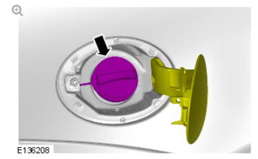
REMOVAL
CAUTION:
Make sure to protect the paintwork.
.14.jpg)
INSTALLATION
.15.jpg)
Body closures fuel filler door assembly (G1393672) removal and installation
REMOVAL
WARNING:
Avoid flames, sparks or lighted substances.
CAUTIONS:
- Extreme cleanliness must be exercised when handling these components.
- Before disconnecting any components, make sure the area is clean and free from foreign material. When disconnected all openings must be sealed.
NOTES:
- Removal steps in this procedure may contain installation details.
- Some variation in the illustrations may occur, but the essential information is always correct.
- Remove the rear wheel.
Refer to: Wheel and Tire (204-04 Wheels and Tires, Removal and Installation).
.16.jpg)
.17.jpg)
.18.jpg)
.20.jpg)
.21.jpg)
CAUTION:
Make sure to protect the paintwork.
NOTE:
Do not disassemble further if the component is removed for access only.
.22.jpg)
INSTALLATION
.23.jpg)
To install, reverse the removal procedure.
READ NEXT:
 Body Closures Liftgate (G1785717)
/ Removal and
Installation
Body Closures Liftgate (G1785717)
/ Removal and
Installation
REMOVAL
CAUTION:
Make sure to protect the paintwork.
NOTE:
Some variation in the illustrations may occur, but the essential
information is always correct.
Disconnect the battery ground cable.
Refer
Body Closures Power
Liftgate Switch (G1889733)
/ Removal and Installation
REMOVAL
NOTE:
Removal steps in this procedure may contain installation details.
CAUTION:
Make sure to protect the paintwork.
NOTE:
Make sure only a suitable plastic tool is used.
INSTALLATION
To i
SEE MORE:
Seat Position Sensor -
Notes on Removal / Replacement
NOTE:
NAS vehicles have a seat position sensor fitted to both the driver and
passenger-side seats.
The seat position sensor, a hall-effect sensor, is fitted to the underside of
both the driver and passenger-side seats on NAS vehicles. It should be
noted that these sensors cannot be re-installed once
Front end Sheet Metal
Repairs Fender
Apron Panel
Front Section (G1775681)
- Removal
REMOVAL
NOTE:
The fender apron panel front section is installed in conjunction with:
Front bumper cover
Hood
Hood hinge
Hood latch panel
Front fender
Fender splash shield
The fender apron panel is serviced as indicated.
Before commencing this procedure make sure that you are aware of
a
© 2019-2026 Copyright www.lrdisc.com
